Fan and shroud assembly

Inactive Publication Date: 2005-03-08
HANON SYST
View PDF12 Cites 34 Cited by
  • Summary
  • Abstract
  • Description
  • Claims
  • Application Information

AI Technical Summary

Benefits of technology

To solve the above and other problems, the present invention provides a fan and shroud assembly which can effe

Problems solved by technology

Thus, the amount of airflow is lost due to the reverse airflow and noise is generated due to the air swirling.
In the above cooling fan, although air suction noise at an edge of the inlet is reduced by the step and the protrusions, noise generated due to swirl at the end tips of the fan blades cannot be reduced.
That is, since air swirling is generated between the end tips of the fan blades and the inner circumferential surface of the path by the rotation of the end tips of the fan blades constituting the rotor, noise is generate

Method used


Image

  • Fan and shroud assembly
  • Fan and shroud assembly
  • Fan and shroud assembly

Examples


Example

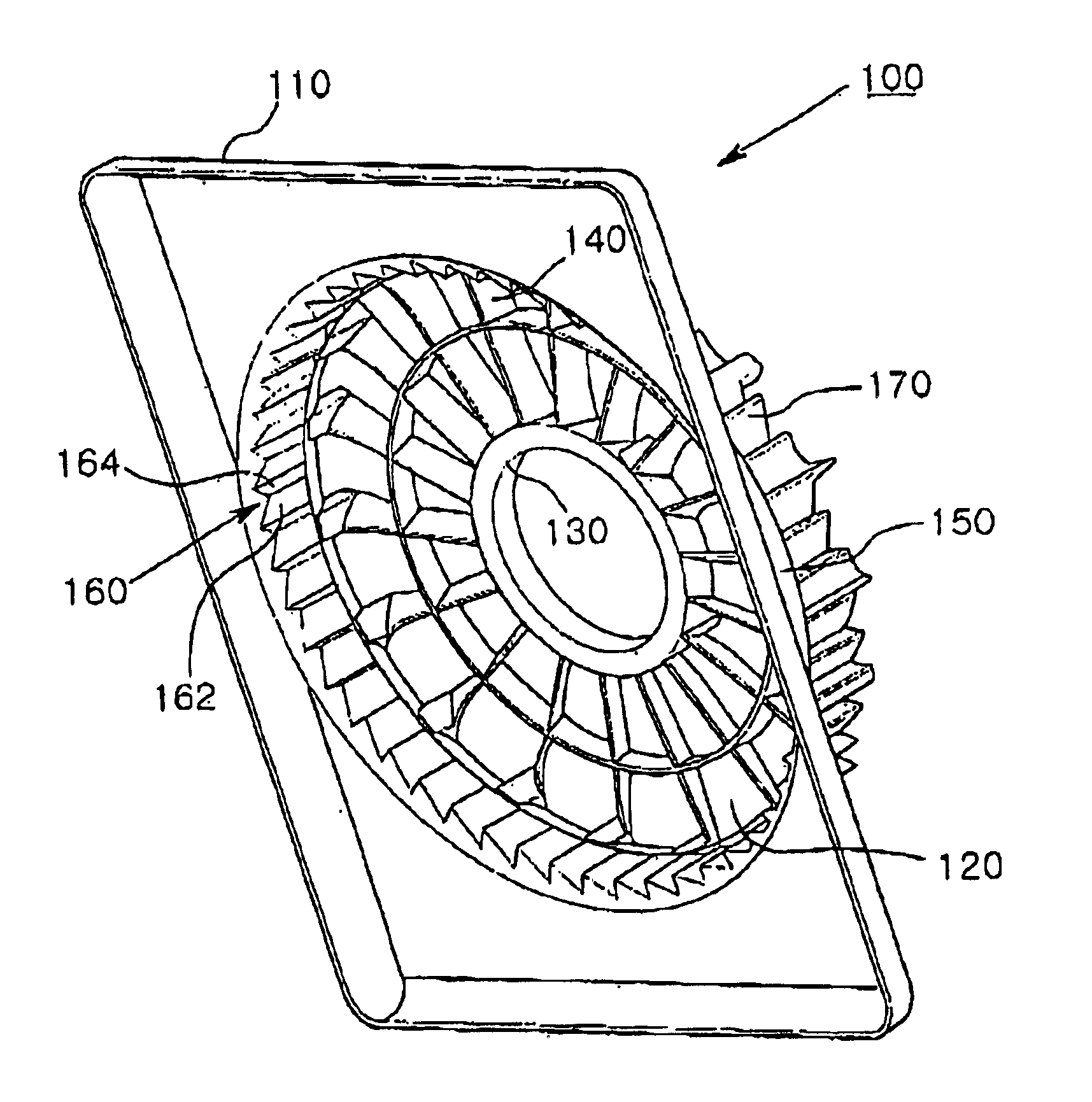
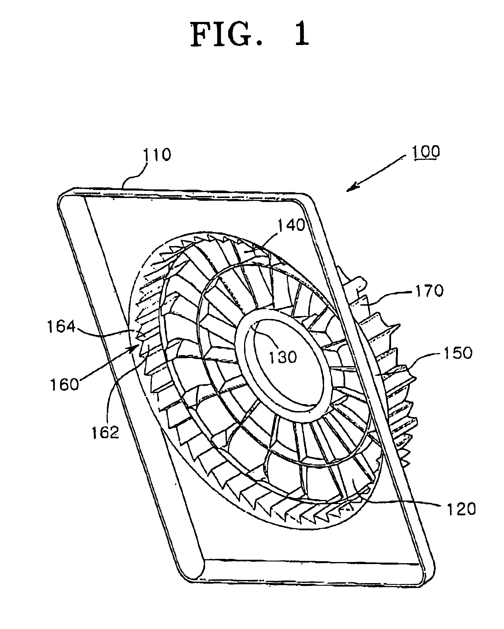
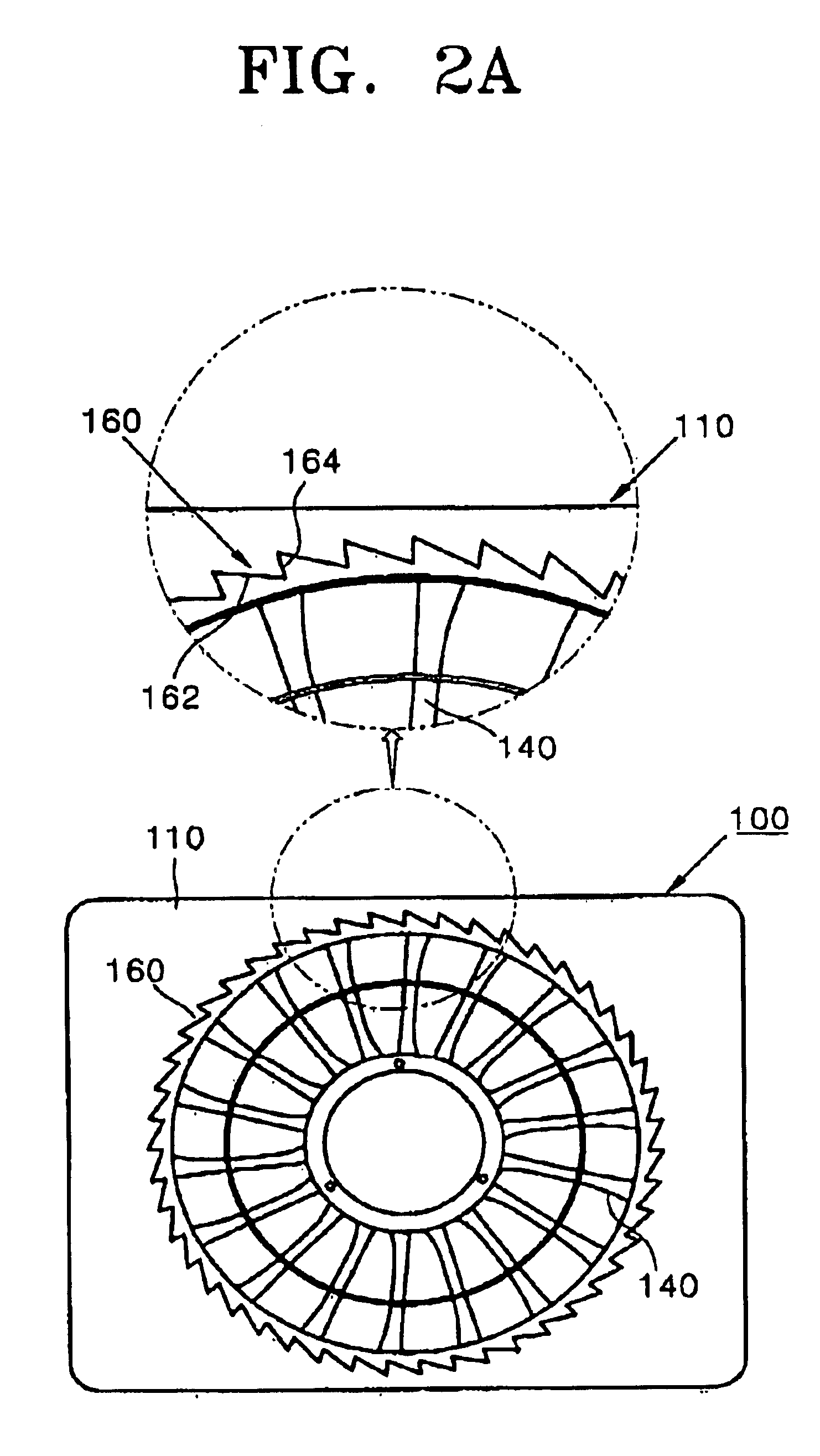
Referring to FIGS. 1 and 2A, a shroud 100 according to the present invention includes a housing 110 having an airflow inlet 120 into which a fan 200 (refer to FIG. 3) is rotatably inserted, a motor support ring 130 supporting a motor (not shown) rotating the fan 200 at the center of the airflow inlet 120 of the housing 110, and a plurality of guide ribs 140 supporting the motor support ring 130 and radially connecting the motor support ring 130 and the housing 110 to guide air exhausted during rotation of the fan 200.

The housing 110 having a shape concaved to the rear thereof so as to effectively guide sucked air toward the airflow inlet. Here, a plurality of coupling ribs (not shown) are formed at the edge of the housing 110 so that the housing 110 is coupled to a heat exchanger.

The airflow inlet 120 is formed by a guide ring portion 150 protruding to the rear of the housing 110. As shown in FIG. 5, a bell mouth 180 bent from the rear end of the guiding ring portion 150 and a plura...


PUM


Abstract

A fan and shroud assembly includes a fan having a hub rotating around one shaft and a plurality of blades extending outwardly from the hub, a shroud encompassing the fan to adjust airflow by rotation of the fan, a guide ring portion located at a position where a predetermined gap exists between the shroud and a circumference connecting end tips of the blades so that the fan is supported by the shroud and rotates, and a plurality of swirl prevention units integrally formed with the guide ring portion to prevent a vortex from proceeding along the circumference in the predetermined gap, each swirl prevention unit having a shape in which the length of a circular arc passing through each of the swirl prevention units with respect to the center of the shroud decreases as the arc is closer to the center of the shroud.

Description

BACKGROUND OF THE INVENTIONThis application claims the priority of Korean Patent Application No. 2002-10389 filed on 27 Feb. 2002 in the Korean Intellectual Property Office, the disclosure of which is incorporated herein in its entirety by reference.1. Field of the InventionThe present invention relates to a fan and shroud assembly, and more particularly, to a fan and shroud assembly in which swirl prevention units are arranged at an airflow inlet of a shroud where a fan is inserted so that swirling of airflow generated during airflow by rotation of the fan is reduced and thus air can be blown with effectively lowered noise.2. Description of the Related ArtAs shown in FIG. 12, a fan 10 used for cooling of a heat exchange medium passing the inside of a heat exchanger such as radiator or condenser of a car includes a hub 11 coupled to a shaft of a driving source such as a motor, and a plurality of blades 12 radially arranged along the outer circumference surface of the hub 11. A fan b...

Claims


Application Information

Patent Timeline
IPC IPC(8): F04D29/08F04D29/16F04D29/66F04D29/52
CPCF04D29/667F04D29/164F04D29/326F04D29/526F04D29/685F04D29/66
Inventor CHO, KYUNG-SEOKMIN, OK-RYULPARK, CHANG-HOPARK, SE-YOUNG
Owner HANON SYST
Why Eureka
Try Eureka