High profile electrical connector

Inactive Publication Date: 2005-03-08
HON HAI PRECISION IND CO LTD
View PDF10 Cites 24 Cited by
  • Summary
  • Abstract
  • Description
  • Claims
  • Application Information

AI Technical Summary

Benefits of technology

An object of the present invention is to provide a high profile electrical

Problems solved by technology

However, the high profile receptacle connector may cause a variety of problem.
For instance, as the complexity of the high profile housing increases, the difficulty of manufacturing the high profile housing increases.
Another proble

Method used


Image

  • High profile electrical connector
  • High profile electrical connector
  • High profile electrical connector

Examples


Embodiment Construction

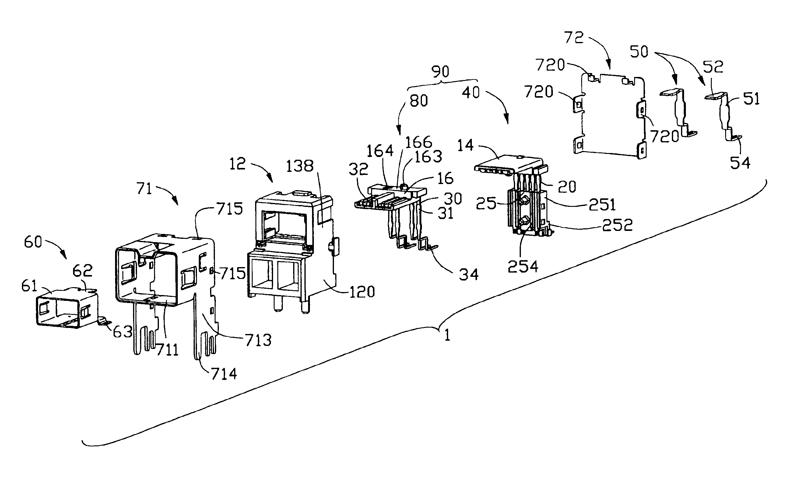
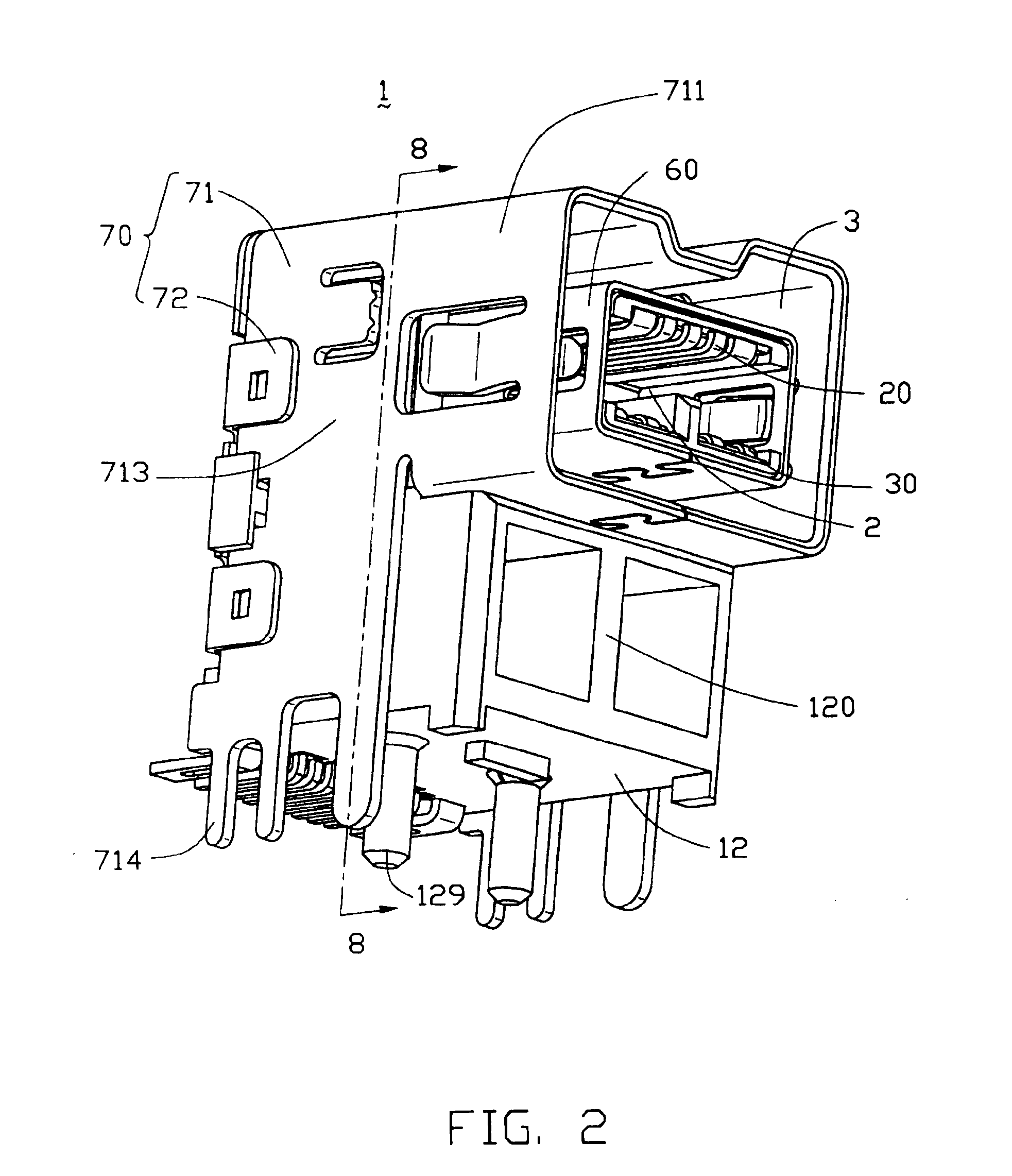
Referring to FIGS. 1 and 2, an electrical connector 1 in accordance with the present invention comprises a dielectric housing 12, a terminal subassembly 90 received in the dielectric housing 12, an inner shield 60 enclosing the terminal subassembly 90, an outer shield 70 enclosing the dielectric housing 12 and a pair of grounding tabs 50 for electrically connecting with the inner shield 60.

Referring to FIG. 3, the dielectric housing 12 comprises a supporting portion 120 and a mating portion 138 located above the supporting portion 120. The supporting portion 120 defines a pair of chambers 1200 in a front face thereof for saving material. A plurality of posts 129 extends downwardly from a bottom face of the supporting portion 120 for being received in corresponding holes of a printed circuit board (PCB, not shown) on which the connector 1 is mounted. The mating portion 138 comprises opposite upper and lower walls 121, 122 and a pair of opposite side walls 123 interconnecting the uppe...


PUM


Abstract

An electrical connector (1) includes a dielectric housing (12), a terminal subassembly (90), an inner shield (60) and an outer shield (70). The dielectric housing (12) includes a supporting portion (120) and a mating portion (138) defining a receiving space (124) above the supporting portion. The terminal subassembly includes first and second terminal modules (40, 80). The first and the second terminal modules respectively include first and second dielectric bodies (14, 16) retained in the receiving space and a number of first and second terminals (20, 30) received in the first and the second dielectric bodies. The first and the second dielectric bodies extend beyond the mating portion (138). The inner shield encloses the first and the second dielectric bodies and defines a first engaging space (2). The outer shield encircles the inner shield. The outer shield and the inner shield define a second engaging space (3) therebetween.

Description

BACKGROUND OF THE INVENTION1. Field of the InventionThe present invention relates to an electrical connector, and particularly to a high profile electrical connector mounted on a printed circuit board.2. Description of Related ArtWith the development of communication and computer technology, electrical connectors for high-speed data transmission are widely used in electronic systems. IEEE1394 (Institute of Electrical and Electronics Engineers; IEEE) connectors are commonly used to connect external and internal peripheral devices to a computer for performing high speed data transmission therebetween. These connectors typically employ a plug connector terminated to a transmission cable and a receptacle connector mounted on a circuit board of the computer.U.S. Pat. No. 6,315,608 discloses a receptacle connector comprising an insulative housing having a base portion and a mating portion, a plurality of conductive terminals retained in the housing, an inner shield enclosing the mating po...

Claims


Application Information

Patent Timeline
IPC IPC(8): H01R13/658H01R12/16H01R12/00H01R12/71
CPCH01R23/6873H01R13/65802H01R13/6582H01R12/00
Inventor ZHU, ZIQIANGHU, JINKUIZHANG, GUOHUA
Owner HON HAI PRECISION IND CO LTD
Why Eureka
Try Eureka