Load receiver and loading stage for a balance, and mass comparator equipped with the load receiver and loading stage

a technology for balancing and load receivers, which is applied in the direction of weighing devices, measuring devices, instruments, etc., can solve the problems of sideways breakage or bendage of the load-receiver arms, and achieve the effect of automatic raising and lowering

Inactive Publication Date: 2005-03-08
METTLER TOLEDO GMBH
View PDF10 Cites 4 Cited by
  • Summary
  • Abstract
  • Description
  • Claims
  • Application Information

AI Technical Summary

Benefits of technology

A particularly preferred embodiment of the inventive mass comparator has a loading stage configured substantially as a circular plate that is rotatably supported at its mid-portion and has at least two loading locations where weight-placement devices are installed. To automate the process of comparative weighing, the loading stage is turned by a motor, and the raising and lowering is also automated. The mounting attachment of the weight-placement devices on the disc of the loading stage is height- and level-adjustable. The loading stage, weight-placement device and / or load receiver are made preferably of a plastic material and / or of metal with a plastic coating. Preferably, the load-receiver frame is freely suspended.

Problems solved by technology

In addition, the load-receiver arms may have sideways breaks or bends.

Method used


Image

  • Load receiver and loading stage for a balance, and mass comparator equipped with the load receiver and loading stage
  • Load receiver and loading stage for a balance, and mass comparator equipped with the load receiver and loading stage
  • Load receiver and loading stage for a balance, and mass comparator equipped with the load receiver and loading stage

Examples


Embodiment Construction

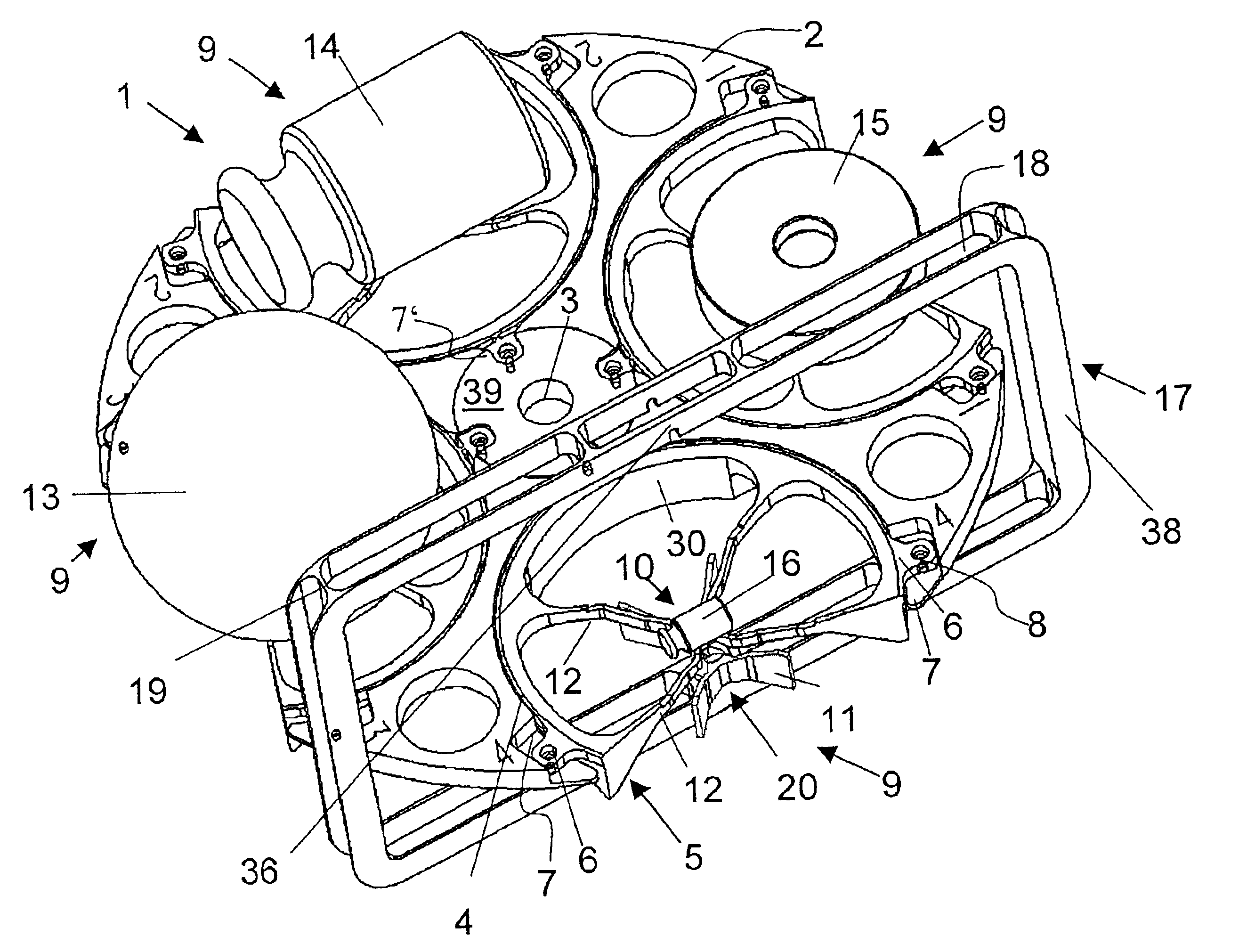
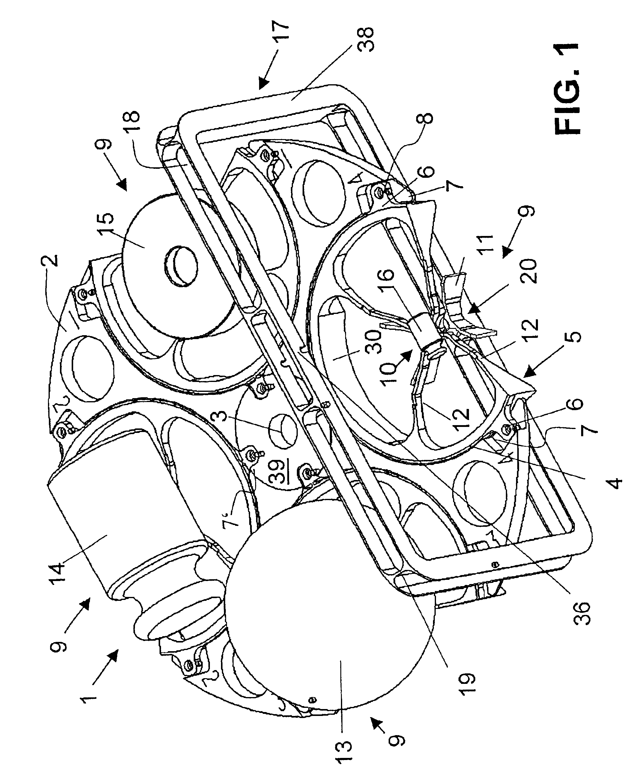
FIG. 1 illustrates a loading stage 1 with four loading locations 9 serving to automatically place test weights on a load receiver. The number of loading locations 9 could, of course, be more or less than four, but the preferred arrangement of the loading locations is in a circle at equal intervals as illustrated. The loading stage 1 consists of a substantially circular disc 2 with an opening 3 through its mid-portion 39. The disc 2 is rotatably supported on a vertical shaft (not shown) passing through the opening 3. At each of the four loading locations 9, the loading stage has a cutout 4 in the shape of a circular segment to receive a weight-placement device 5. Each weight-placement device 5 has three fastening lugs 6 that fit into recesses 7, 7′ of the loading stage 1 and serve to fasten the weight-placement devices 5 to the loading stage 1. The fastenings lugs 6 pointing towards the mid-portion 39 are fastened in recesses 7′ which have a defined vertical depth that defines a refe...


PUM


Abstract

A load receiver (10) for a balance with arms (11) is designed to support weights of various shapes and sizes (13, 14, 15, 16) by cradling the weights in a depression sloped at a variable slope angle towards the middle of the load receiver. A loading stage (1) arranged to cooperate with the load receiver (10) has one or more weight-placement devices (5) designed so that the load receiver (10) can reach through the weight-placement device (5) without touching the latter. The loading stage (1) and the load receiver (10) are moveable up and down in relation to each other. The weight-placement device (5) is suitably configured to support the different weights (13, 14, 15, 16). The load receiver (10) and loading stage (1) are used in a mass comparator for testing weight standards with a high degree of precision.

Description

BACKGROUND OF THE INVENTIONThe invention relates to a load receiver and a loading stage, and it also relates to a balance, particularly a mass comparator, that is equipped with the inventive load receiver and / or loading stage. The load receiver has an arrangement of narrow ridges and a horizontal receiving surface for a weight, with a depression or concavity so that the center of the load receiver is lower than the peripheral portions. The loading stage supports at least one weight-loading device, which can be connected to the loading stage and is shaped so that the load receiver reaches from below through the weight-loading device without touching the latter. The loading stage and the load receiver are movable up and down in relation to each other.A load receiver with a funnel-shaped depression at the center as disclosed in U.S. Pat. No. 5,332,870 is designed for the specific purpose of weighing flat filters. The conical surface of the load receiver consists of a net or a metal foi...

Claims


Application Information

Patent Timeline
Patent Type & Authority Patents(United States)
IPC IPC(8): G01G21/00G01G23/01G01G21/22G01G23/00G01G21/26G01G1/34
CPCG01G23/01G01G21/22
Inventor WEBER, RENE
Owner METTLER TOLEDO GMBH
Why Eureka
Try Eureka