Equipment fan

a technology of equipment fans and components, applied in the field of equipment fans, can solve the problems of difficult replacement of the fan, e.g. for a repair, and achieve the effect of quick replacement of any failing components

Inactive Publication Date: 2005-03-08
EBM PAPST ST GEORGEN & -
View PDF31 Cites 10 Cited by
  • Summary
  • Abstract
  • Description
  • Claims
  • Application Information

AI Technical Summary

Benefits of technology

[0004]It is therefore an object of the invention to provide a modular fan

Problems solved by technology

Equipment fans are often installed in inaccessible locations where su

Method used


Image

  • Equipment fan
  • Equipment fan
  • Equipment fan

Examples


Embodiment Construction

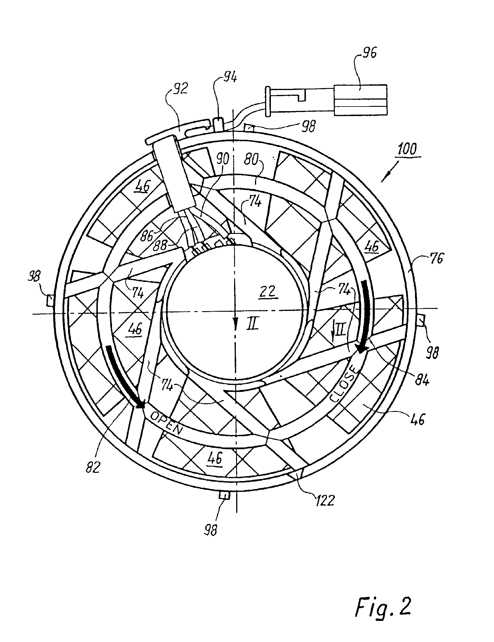
in the direction of an arrow XII of FIG. 13;

[0020]FIG. 13 is a side view, viewed in the direction of arrow XIII of FIG. 12;

[0021]FIG. 14 is a plan view, viewed in the direction of arrow XIV of FIG. 13;

[0022]FIG. 15 is a side view, depicted partly in section, which depicts the routing of the electrical connecting lines; and

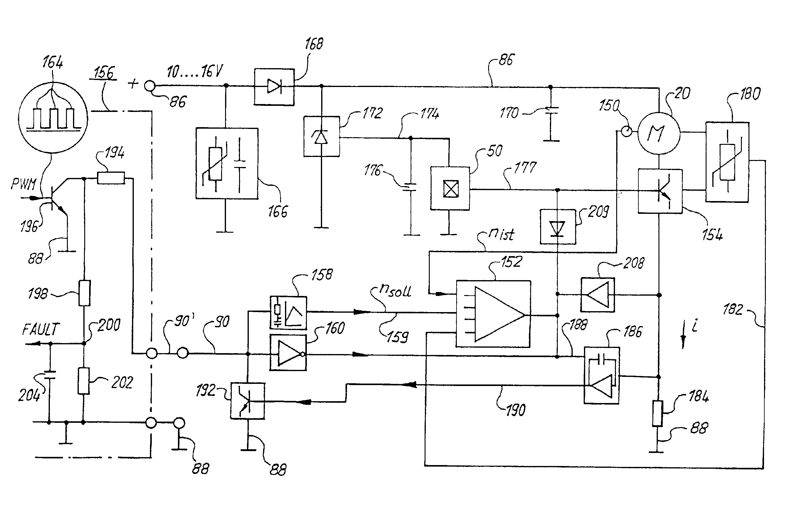
[0023]FIG. 16 shows a preferred exemplary embodiment of apparatus 150 of FIG. 11.

DETAILED DESCRIPTION OF THE PREFERRED EMBODIMENTS

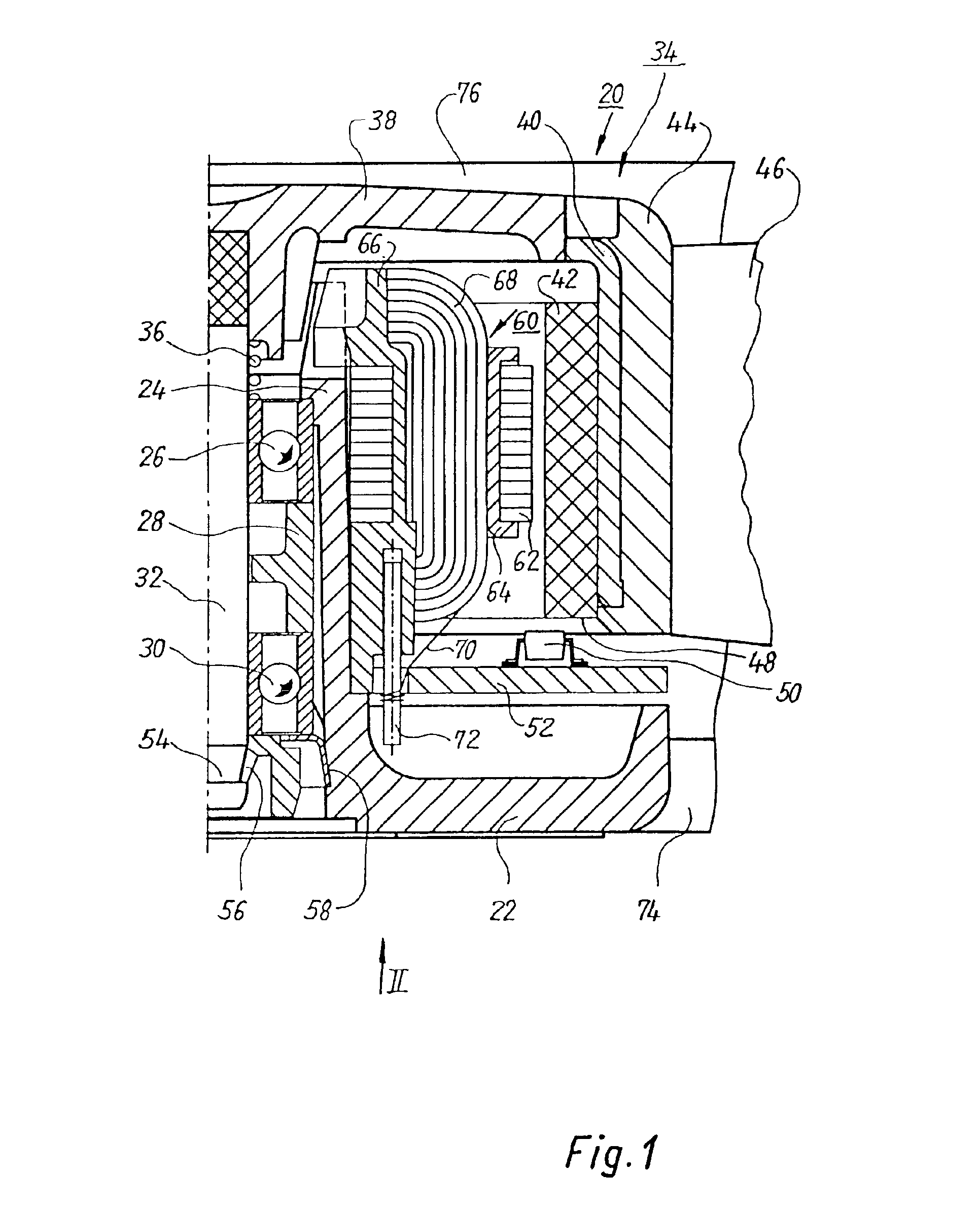
[0024]FIG. 1 shows a greatly magnified section through the right half of an external-rotor motor 20, the left half being essentially mirror-symmetrical thereto. To save drawing space, fan blade 46 and strut 74 are shown broken away. The motor has a hub 22, made of a suitable plastic, that is configured integrally with a bearing support tube 24 in which an upper ball bearing 26, a spacer 28 for the outer races, and a lower ball bearing 30 are arranged, which ball bearings support central shaft 32 of an external rotor 34. The inner races o...


PUM


Abstract

An improved fan useful for ventilating applications in motor vehicles features a modular structure, which facilitates quick replacement of any components likely to fail. A first module (110) is intended for permanent installation on the part that is to be cooled. A second module (110) is configured for quick engagement to and disengagement from the first module. The second module preferably comprises a hub (22; 362), an internal stator (60; 332) mounted on the hub, and one or more struts (74; 344) connecting the hub to a cylindrical casing part (76; 336) which surrounds but is spaced from the outside of the fan wheel (46; 348). The struts form a lattice (112) which can be easily grasped for swapping out the second module when repair or replacement becomes necessary. The fan has a Hall sensor (50) and a control circuit (156) which regulates fan speed according to PWM (Pulse Width Modulation) or DC voltage signals (164) supplied from outside and has means (186; 244) for generating a fault signal in the event of a fault state, and for sending the fault signal out on a control line (90).

Description

FIELD OF THE INVENTION[0002]The invention concerns, inter alia, an equipment fan having a fan wheel that is driven by an external-rotor motor whose internal stator is mounted on a hub. The invention preferably concerns a fan of this kind that can communicate with an external control device via a control line (“bus”).BACKGROUND[0003]Equipment fans are often installed in inaccessible locations where subsequent replacement of the fan, e.g. for a repair, is very difficult. This applies in particular to land and water vehicles and aircraft.SUMMARY OF THE INVENTION[0004]It is therefore an object of the invention to provide a modular fan structure which facilitates quick replacement of any failing components.[0005]According to the invention, this object is achieved by providing a housing containing non-wearing components, which releasably engages a replaceable module including an external rotor, fan wheel, a hub, an internal stator mounted on the hub, and at least one strut connecting the ...

Claims


Application Information

Patent Timeline
IPC IPC(8): F04D25/06F04D25/02F04D29/60
CPCF04D25/0613F04D29/601Y10S388/903
Inventor HEYDT, THOMAS VON DER
Owner EBM PAPST ST GEORGEN & -
Why Eureka
Try Eureka