Switched reactance modulated E-class oscillator design

a technology of reactance modulation and oscillator, which is applied in the direction of pulse manipulation, pulse technique, therapy, etc., can solve the problems of significant physical limits on the general principles of power, data transmission and packaging, and stringent requirements, and achieve high resonant operation, power efficiency, and rapid amplitude modulation

Inactive Publication Date: 2005-03-08
ALFRED E MANN INST FOR BIOMEDICAL ENG AT THE UNIV OF SOUTHERN CALIFORNIA
View PDF60 Cites 50 Cited by
  • Summary
  • Abstract
  • Description
  • Claims
  • Application Information

AI Technical Summary

Benefits of technology

The present invention overcomes these, and other, problems by providing novel oscillator designed to accommodate the stringent requirements of BIONs as discussed above. More specifically, the present invention involves a novel Class E modulated transmitter capable of compensating for the weak coupling coefficient between a BION's receiving coil and the corporeal antenna's primary coil, accommodating fluctuations in the inductance of the external coil that arise when the BION's flexible shape is deformed while being worn by a patient, providing highly resonant operation for power efficiency, and providing rapid amplitude modulation to transmit data from the BION.

Problems solved by technology

Achieving such efficiency, however, is problematic for a number of reasons.
BION implants are about 100 times smaller in volume than conventional implantable electronic devices such as cardiac pacemakers and cochlear implants, resulting in significant physical limits on the general principles of power, data transmission and packaging fundamental to operation of BIONs.
Unfortunately, the small, narrow shape of BIONs has resulted in stringent requirements for wireless power and data transmission and electromechanical assembly.
Developing solutions to meet these requirements has been difficult.
For example, the inductive coupling between a primary inductive coil within an extracorporeal antenna utilized to power a BION and a small, secondary inductive coil within the BION itself is difficult to establish and maintain within the stringent requirements of the BION's power, data transmission, and electromechanical assembly.
However, the very nature of the BION's necessarily small size establishes strict limits on the BION's receiving coil size.
However, selection of an appropriate oscillator to generate sufficient field strength has been problematic.
Conventional A-Class amplifiers are not efficient enough for field use, as they exhibit significant power dissipation.
Although the high field strength and low power dissipation requirements of BION applications, in general, might be accomplished by using a Class E amplification with a very high Q (>100) tuned circuit, it has been unclear how to effectively utilize a Class E oscillator in a BION application, because of the BION's two other previously mentioned requirements: power efficiency and data transmission.
These requirements are fundamentally in conflict, as power efficiency requires highly resonant operation of the Class E oscillator, while data transmission requires rapid amplitude modulation of the Class E oscillator.
With respect to the rapid amplitude modulation in particular, a problematic feature of the Class E oscillator, in BION applications, is that both the position and duration of the drive pulse are critical.
However, producing various pulse widths requires additional components that increase the cost and size of the coil driver assembly, which is impractical in BION applications.
In addition to these complications, using a Class E oscillator in BION applications causes additional problems.
Such deformities will cause fluctuations in the inductance of the external coil, and a Class E oscillator does not inherently accommodate such fluctuations.
This type of construction makes a typical Class E oscillator unsuitable for BION applications.
Further, complicated circuitry is required to change pulse width for achieving desired AM modulation, when utilizing a typical Class E oscillator.
Changes in pulse width are undesirable because they cause significant degradation of efficiency, something a battery-operated BION has limited capacity to endure.

Method used


Image

  • Switched reactance modulated E-class oscillator design
  • Switched reactance modulated E-class oscillator design
  • Switched reactance modulated E-class oscillator design

Examples


Embodiment Construction

In the following description of the preferred embodiments reference is made to the accompanying drawings which form the part thereof, and in which are shown by way of illustration specific embodiments in which the invention may be practiced. It is to be understood that other embodiments may be utilized and structural and functional changes may be made without departing from the scope of the present invention.

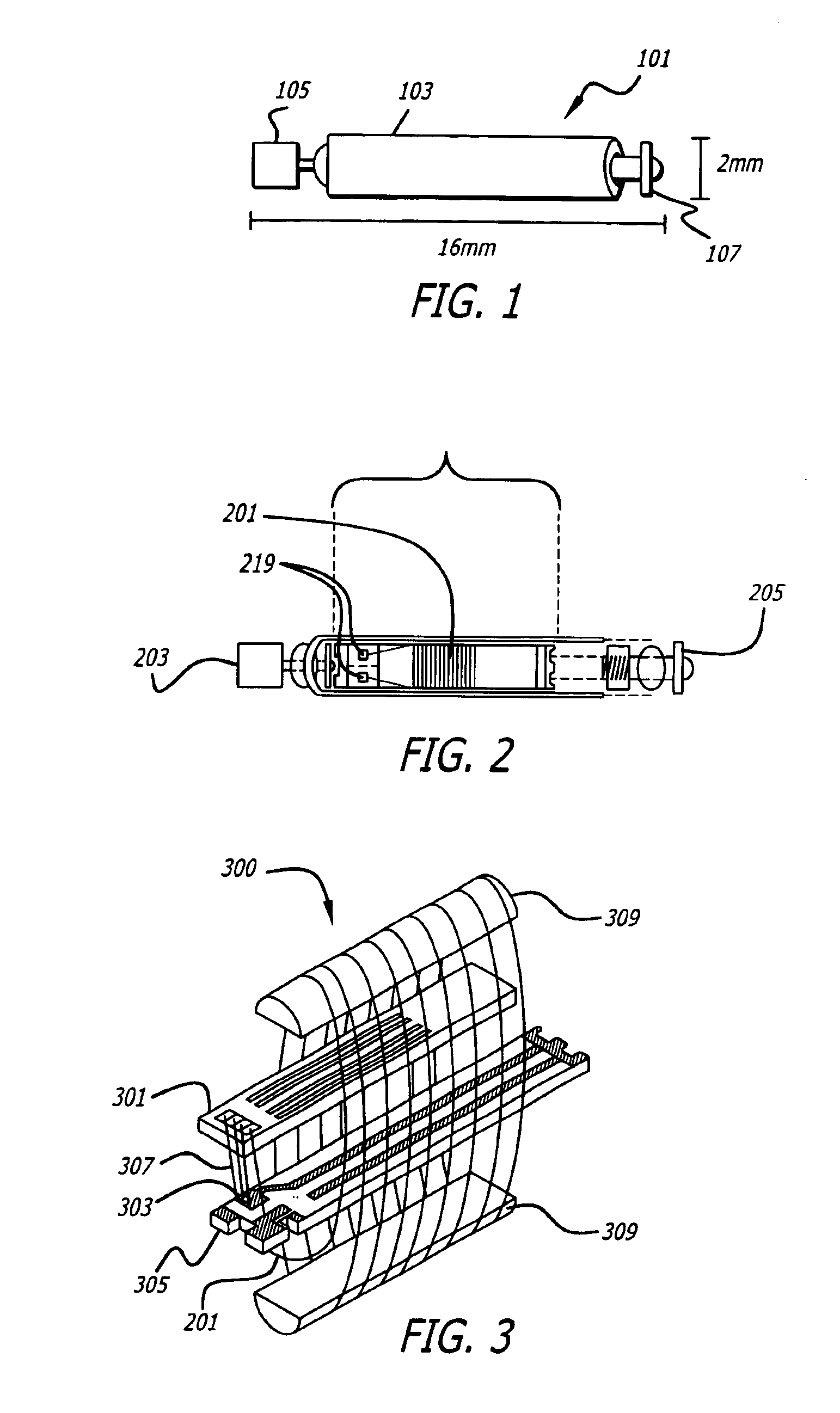
FIG. 1 illustrates a BION 101 and its typical size. Encased in a glass sheath 103 and having two electrodes, a Ta electrode 105 and an Ir electrode 107, BION 101 has a typical size of 2 mm in diameter and 16 mm in length. The small size is important, because it allows BIONs to be implanted by injection in an outpatient procedure that can be performed by any physician. Further, their small size allows them to be placed in small, deep, or hard-to-reach muscles that are impossible to stimulate selectively from the skin surface. Further, the small size and wireless nature of implant...


PUM


Abstract

A modulated Class E transmitter is disclosed. In one embodiment of the invention, the modulated Class E oscillator achieves high coil currents (˜1A) and voltages (˜500V) with low power components by precisely timed injection of current when the oscillating current in the inductor passes through zero. A detector circuit is used to trigger the current injection at the appropriate instant regardless of changes in the resonant frequency of the system. Its phase can be adjusted to compensate for propagation delays in the drive circuitry, while amplitude modulation is accomplished by switching in additional reactive conductance to increase the current injected into the tank circuit.

Description

BACKGROUND OF THE INVENTION1. Field of the InventionThis invention relates to drive coils designed to supply a powerful magnetic field to supply power and operational commands to a mismatched, spacially remote receiving coil. More particularly, the invention relates to methods and circuits for efficiently driving a resonating transmitting coil by efficient modulation of the carrier, wherein the modulation can be either amplitude modulation or frequency modulation.2. General Background and State of the ArtMany applications require or would benefit from improved efficiency in L-C tank circuit oscillations. Achieving such efficiency, however, is problematic for a number of reasons. Such problems may be illustratively presented in the context of a particular, exemplary application. Therefore, although there are many applications which would benefit from an efficiently driven oscillator, the description herein will continue with particular reference to a single exemplary application invo...

Claims


Application Information

Patent Timeline
Patent Type & Authority Patents(United States)
IPC IPC(8): A61N1/08A61N1/372A61N1/378H02J17/00H03B5/12H03C1/12
CPCA61N1/08A61N1/3727A61N1/37223A61N1/37211
Inventor MOORE, WILLIAM HENRY
Owner ALFRED E MANN INST FOR BIOMEDICAL ENG AT THE UNIV OF SOUTHERN CALIFORNIA
Why Eureka
Try Eureka