Liquid crystal display device

a liquid crystal display and display device technology, applied in the field of liquid crystal display devices, can solve the problems of shortening the luminance of the displayed image, deteriorating visibility and attention-calling function of the display device,

Inactive Publication Date: 2005-03-08
YAZAKI CORP
View PDF19 Cites 128 Cited by
  • Summary
  • Abstract
  • Description
  • Claims
  • Application Information

AI Technical Summary

Benefits of technology

Further, the present invention provides a liquid crystal display device including an under light type back light unit in which light emitted from a plurality of linear light sources is reflected by a reflecting sheet disposed at a rear side of the plurality of linear light sources, then transmitted through a light modulation film and a light diffusion plate to form a planar light source with a uniform luminance thereby to indirectly irradiate a liquid crystal panel from a rear side thereof, wherein one end portion of the light modulation film is shielded by a light shielding plate, and light emitted from one of the plurality of linear light sources is shielded by the light shielding plate and transmitted through only the light diffusion plate thereby to directly irradiate with a higher luminance on a part of a display area of the liquid crystal panel than that of another part of the display area.

Problems solved by technology

In the aforesaid conventional examples, since the luminance of the displayed image of the LCD is reduced to about 150 cd / m2 due to the attenuation, the shortage of the luminance of the displayed image arises.
Therefore, the aforesaid conventional LCDs are disadvantageous in that the visibility and the attention calling function thereof are deteriorated when used for a particular object such as a vehicle-mounted alarm display.

Method used


Image

  • Liquid crystal display device
  • Liquid crystal display device
  • Liquid crystal display device

Examples


Embodiment Construction

The LCDs according to the embodiments of the present invention will be described in detail with reference to the accompanying drawings. In the following embodiments, elements same as or common to those of the conventional LCDs shown in FIGS. 4 and 5 are designated by the same reference characters and the explanation thereof is omitted.

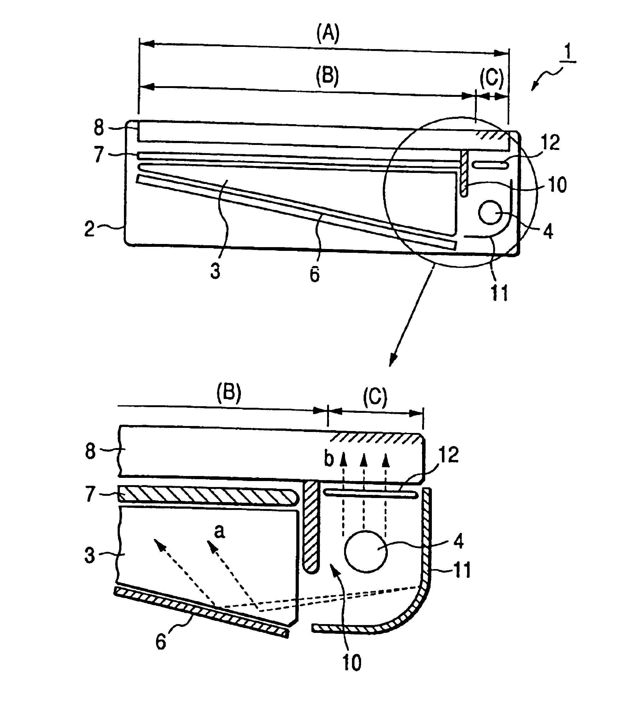
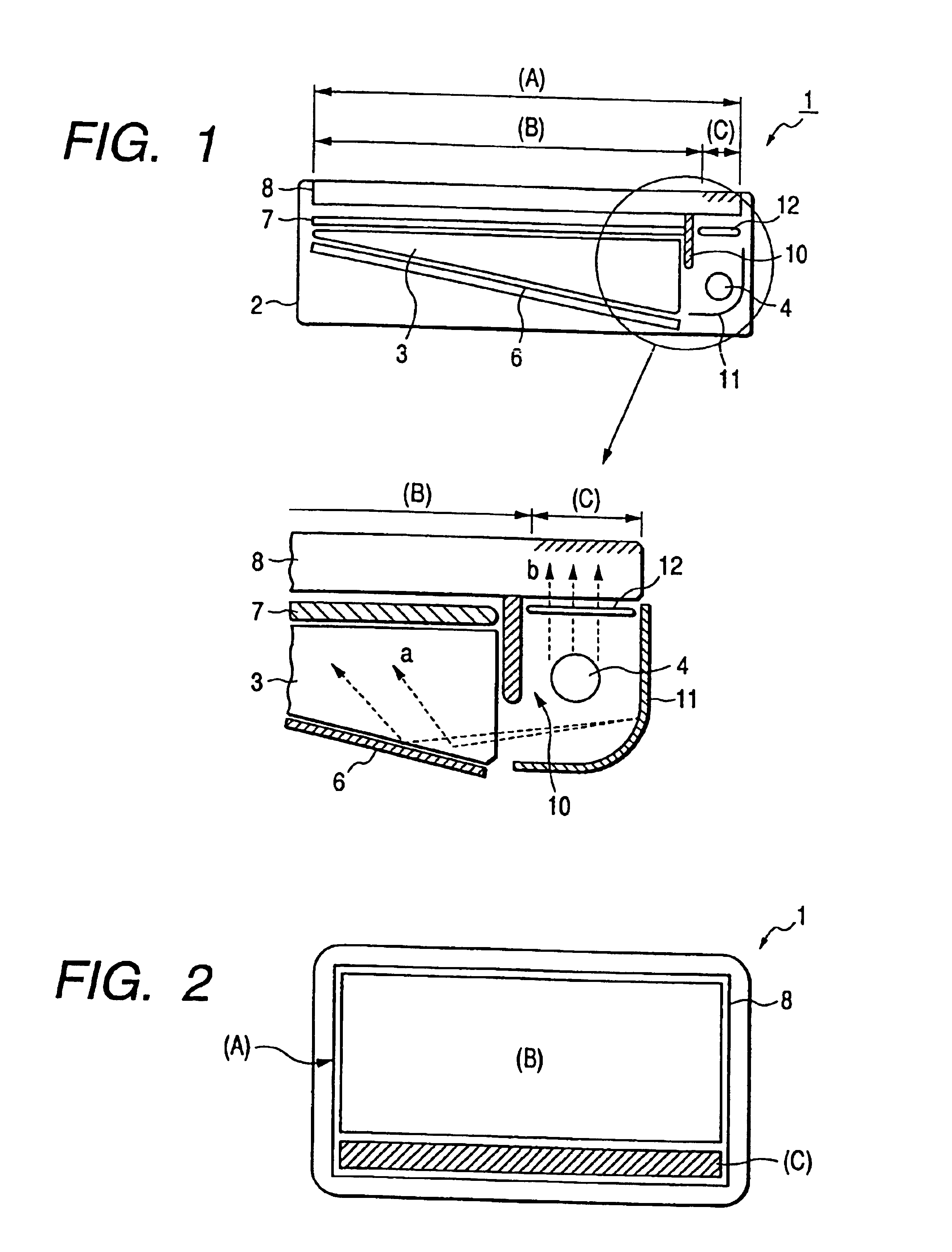
FIG. 1 is a sectional side view of an LCD 1 according to the first embodiment and further shows the main portion thereof (circled portion) in an enlarged scale. In this case, the upper surface portion and the lower surface portion of the LCD 1 are respectively shown in the upper and lower directions in the figure, like the conventional examples shown in FIGS. 4 and 5. The LCD 1 according to the embodiment is arranged to have an edge light type back light unit.

A light conduction plate 3 disposed at the center portion of a housing 2 is formed by transparent resin material or the like so that each of the upper and lower surfaces thereof is formed to be fl...


PUM

PropertyMeasurementUnit
luminanceaaaaaaaaaa
luminanceaaaaaaaaaa
luminanceaaaaaaaaaa

Abstract

An LCD provided with an edge light type back light unit which is arranged in a manner that the light emitted from a CCT in the form of a linear light source is condensed at the end portion of a light conduction plate, then the light reflected by a reflecting sheet and then ejected from the light conduction plate transmits through a light diffusion plate thereby to indirectly irradiate on a liquid crystal panel from the rear direction thereof in the form of planar light with uniform luminance. A light reflecting plate having a curved surface is disposed in the vicinity of the CCT. A light shielding plate is disposed in a manner that a part of the light emitted from the CCT and reflected by the light reflecting plate is condensed at the end portion of the light conduction plate. Another part of the light emitted from the CCT and reflected by the light reflecting plate is directed upward and directly irradiates a part of the display area of the liquid crystal panel thereby to form a high luminance irradiation portion. Accordingly, thus configured LCD is improved in its visibility and so can be formed as a vehicle-mounted alarm display device for displaying various alarms.

Description

BACKGROUND OF THE INVENTION1. Field of the InventionThe present invention relates to a liquid crystal display device (LCD) intended to increase the luminance of a display screen thereof so as to be suitable for an alarm display device to be mounted on a vehicle such as an automobile or the like.2. Description of the Related ArtFIG. 4 is a sectional side view of a lighting unit and a liquid crystal display device using it described in Japanese Patent Unexamined Publication No. Hei. 9-281492. In this case, a back light unit called an edge light type or a side light type using a light conduction plate 3 is employed as a lighting unit for irradiating a liquid crystal panel 8 of an LCD 1.A housing 2 having an upper surface portion and a lower surface portion respectively shown in the upper and lower directions in the figure is provided with the light conduction plate 3 made of light transmission material at the center portion thereof. A fluorescent tube (hereinafter referred to as a CCT)...

Claims


Application Information

Patent Timeline
Patent Type & Authority Patents(United States)
IPC IPC(8): F21V8/00G02F1/1335G02F1/13G02B6/00G02F1/13357
CPCG02B6/0023G02B6/0031G02F1/133615G02B6/0055G02B6/0046G02B6/0068G02B6/0051
Inventor MATSUSHITA, JUNICHIAOKI, KUNIMITSU
Owner YAZAKI CORP
Why Eureka
Try Eureka