Eureka AIR delivers breakthrough ideas for toughest innovation challenges, trusted by R&D personnel around the world.

Integrated image-reading/writing head and image processing apparatus incorporating the same

Inactive Publication Date: 2005-03-08
ROHM CO LTD
View PDF18 Cites 15 Cited by
  • Summary
  • Abstract
  • Description
  • Claims
  • Application Information

AI Technical Summary

Benefits of technology

According to this integrated image-reading / writing head, each of the light receiving elements and the heating elements are mounted on a same single surface of the substrate. In other words, according to this integrated image-reading / writing head, operations necessary for mounting the light receiving elements and the light emitting elements are performed only to one same surface of the substrate. Therefore, differing from manufacture of the prior-art integrated image-reading / writing head, there is no longer the need for first mounting the light receiving elements on one surface of the substrate, then turning the substrate over, and then mounting the light emitting elements on the other surface of the substrate. As a′ result, according to the integrated image-reading / writing head having the above described constitution, manufacturing efficiency of the integrated image-reading / writing head can be improved over that of the prior art.
With this arrangement, once the lid member is operated to expose the opening, the integrated image-reading / writing head is already removed from the box. Thus, the same advantages can be enjoyed as in the arrangement in which the integrated image-reading / writing head is pivotable. These advantages include easy replacement and repair of parts and components, replacement of roll paper, as well as removing a stuck piece of paper.

Problems solved by technology

Specifically, according to the image processing apparatus incorporating the integrated image-reading / writing head X, the platen roller P1 for feeding the document is disposed above the integrated image-reading / writing head X whereas the platen roller P2 for feeding the recording paper is disposed below the integrated image-reading / writing head X. Therefore, in this image processing apparatus, due to the disposition of the platen rollers P1, P2, it is difficult to reduce an overall size of the image processing apparatus by decreasing a vertical dimension.

Method used


Image

  • Integrated image-reading/writing head and image processing apparatus incorporating the same
  • Integrated image-reading/writing head and image processing apparatus incorporating the same
  • Integrated image-reading/writing head and image processing apparatus incorporating the same

Examples


eleventh embodiment

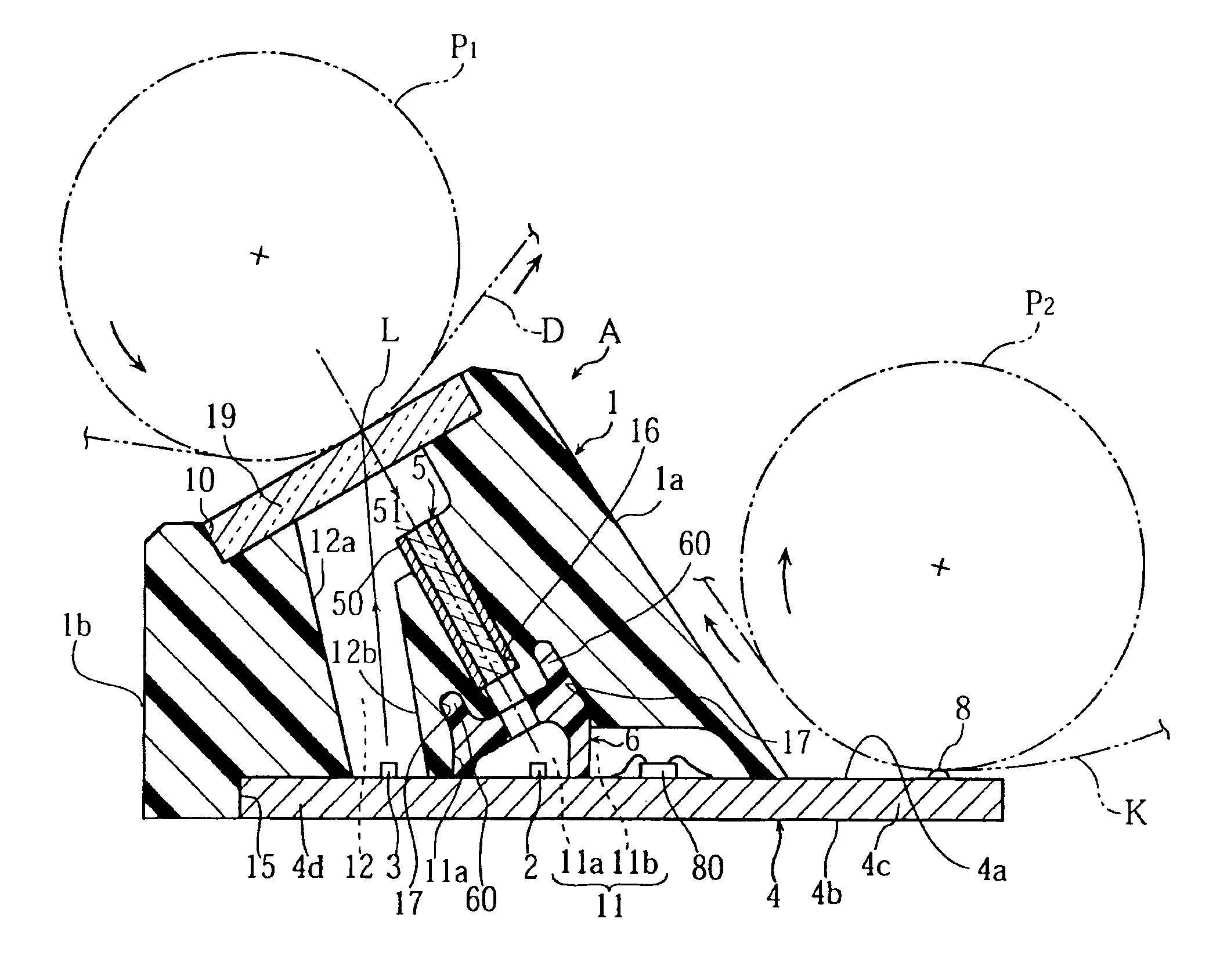
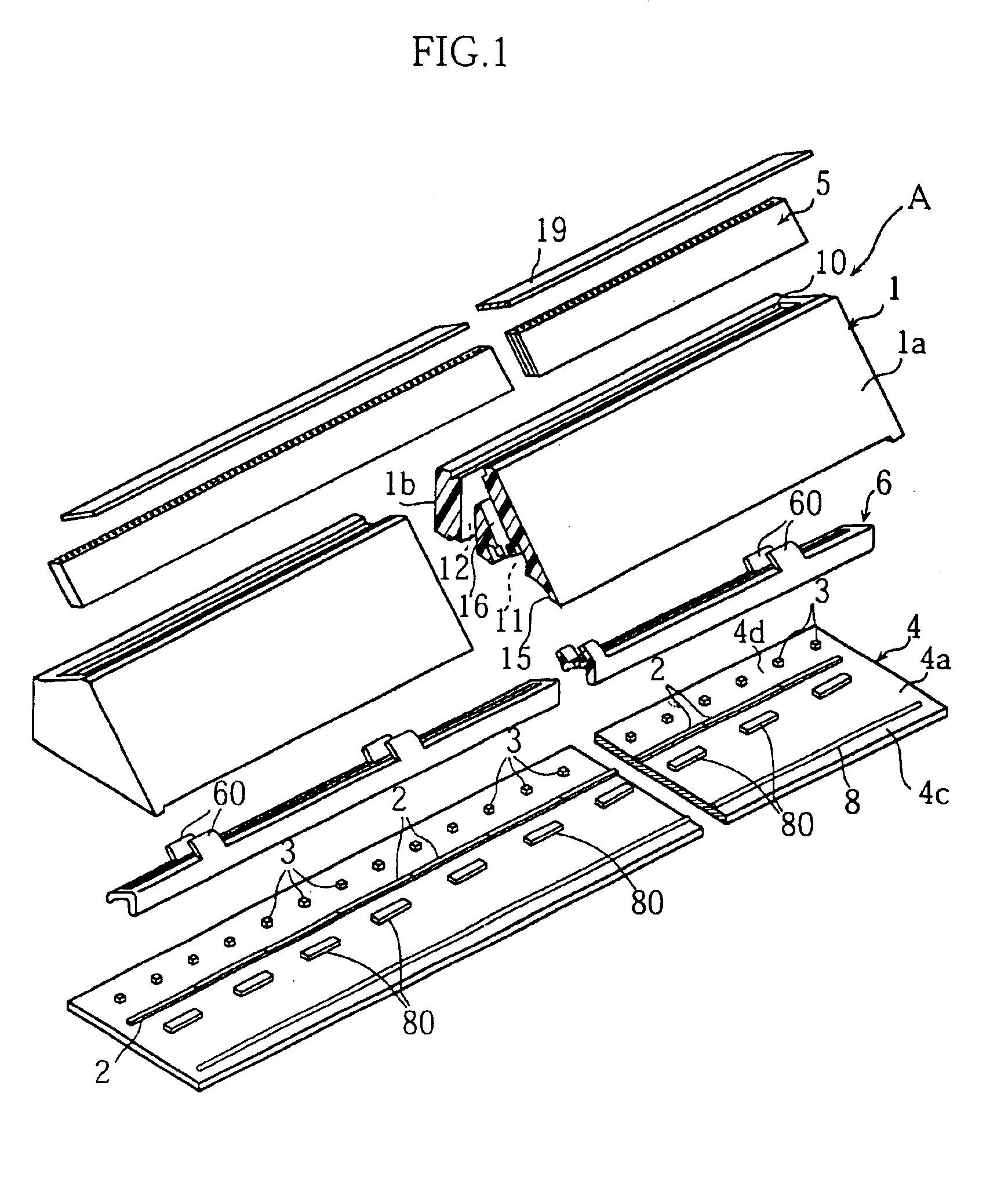
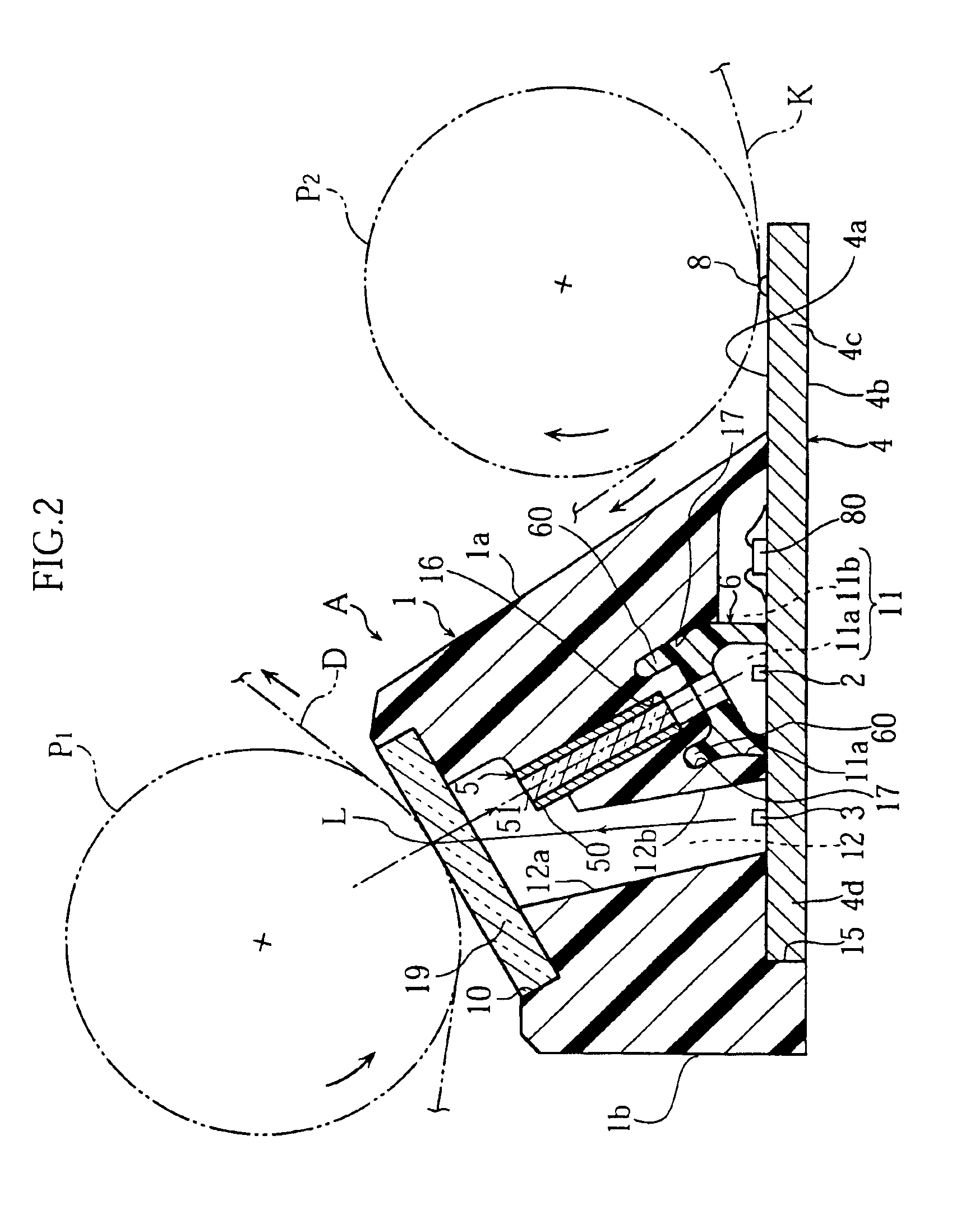
FIG. 16 to FIG. 23 show an image processing apparatus as the present invention.

Similarly to the tenth embodiment described above, an integrated image-reading / writing head A according to the eleventh embodiment differs from the first embodiment in that location of the light source elements 3 and location of the sensor IC chips 2 in the substrate 4 are swapped. Accordingly, layout and use of the space formed in the case 1 are also different between the first embodiment and the eleventh embodiment, but there are no essential differences. The rest of the arrangement in the eleventh embodiment is identical with that of the first embodiment. Therefore, hereinafter, description will cover primarily differences from the first embodiment, i.e. disposition of the elements in the substrate 4 and wiring patterns in the substrate 4. The members and elements essentially the same as in the first embodiment will be indicated by the same alpha-numeral codes without detailed description.

As clearly sh...


PUM


Abstract

An integrated image-reading / writing head A comprises an oblong rectangular substrate (4) having a first longitudinal edge portion (4c), a second longitudinal edge portion (4d) and a surface (4a) mounted with an array of light receiving elements (2) and an array of drive IC's (80). The surface (4a) of the substrate (4) is fitted with an oblong case (1) enclosing therein the light receiving elements (2) and the drive IC's (80). The first longitudinal edge portion (4c) of the substrate (4) is extended out of the case by a predetermined width. The surface (4a) of the substrate (4) is further mounted with a light source (3) enclosed within the case (1). A plurality of heating elements (8) are mounted on a region of the surface (4a) of the substrate (4) extended out of the case (1).

Description

TECHNICAL FIELDThe present invention relates to an integrated image-reading / writing head having both image reading capability and image forming capability, and an image processing apparatus incorporating the same.BACKGROUND ARTAn image processing apparatus such as a facsimile machine has to have both image reading capability and image forming capability, and further has to meet requirement for a smaller size of the image processing apparatus. With this background, there is already made a proposal that an integrated image-reading / writing head capable of performing both image reading and image forming should be incorporated in the image processing apparatus. An integrated image-reading / writing head of this kind has a constitution as shown in FIG. 24 for example. The integrated image-reading / writing head X shown in this figure comprises a case 1A having an upper opening 10A fitted with a transparent cover 19A. Inside the case 1A, there is a light source 3A for illuminating a reading li...

Claims


Application Information

Patent Timeline
IPC IPC(8): H04N1/024H04N1/12
CPCH04N1/024H04N1/02463H04N1/02427H04N1/1215H01L2224/05554H01L2224/49175
Inventor FUJIMOTO, HISAYOSHIONISHI, HIROAKITAKAKURA, TOSHIHIKOIMAMURA, NORIHIRO
Owner ROHM CO LTD
Why Eureka
Eureka Blog
Learn More