Eureka AIR delivers breakthrough ideas for toughest innovation challenges, trusted by R&D personnel around the world.

Track and Sprocket Drive for Drilling

a technology of track and sprocket, which is applied in the direction of drilling rods, drilling pipes, rotary drilling, etc., can solve the problems of limited horizontal runs produced by conventional devices and methods, affecting the performance of drilling rigs, so as to facilitate assembly and repair the effect of damaged parts and easy replacemen

Inactive Publication Date: 2010-08-05
TARGET DRILLING
View PDF22 Cites 34 Cited by
  • Summary
  • Abstract
  • Description
  • Claims
  • Application Information

AI Technical Summary

Benefits of technology

[0012]An object of the present invention is to provide a drive system for a top drive carriage that precisely and efficiently moves the top drive carriage along a mast. The mast may include multiple sections that are easily assembled in the field. Another object of the present invention is to guide the top drive carriage without the use of additional guide rails. In addition, it is a further object of the present invention to provide a drive system for a top drive carriage that allows for easy replacement and repair of damaged parts.
[0014]Each of the plurality of bushings may be attached to the spaced apart track plates by a bolt and nut arrangement. In addition, each of the first track and the second track may further include wear plates positioned adjacent to the plurality of bushings to prevent wear on the track plates. At least one first roller configured to move with the top drive carriage assembly may be provided adjacent to an outer edge of the spaced apart track plates of the first track, and at least one second roller configured to move with the top drive carriage assembly may be provided adjacent to an outer edge of the spaced apart track plates of the second track.
[0017]Each of the plurality of bushings may be attached to the spaced apart track plates by a bolt and nut arrangement. In addition, the track may further include wear plates positioned adjacent to the plurality of bushings to prevent wear on the track plates. The at least one sprocket arrangement may be driven by a planetary gear arrangement driven by a hydraulic motor. The sprocket arrangement may be manufactured using a water jet technique.
[0019]Each of the plurality of bushings may be attached to the spaced apart track plates by a bolt and nut arrangement. In addition, each of the first track and the second track may further include wear plates positioned adjacent to the plurality of bushings to prevent wear on the track plates. At least one first roller configured to move with the top drive carriage assembly may be provided adjacent to an outer edge of the spaced apart track plates of the first track, and at least one second roller configured to move with the top drive carriage assembly may be provided adjacent to an outer edge of the spaced apart track plates of the second track. The at least one sprocket arrangement may be driven by a planetary gear arrangement driven by a hydraulic motor. The top drive carriage assembly may include four sprocket arrangements. Two of the sprocket arrangements may be operatively engaged with the first track and two of the sprocket arrangements may be operatively engaged with the second track.

Problems solved by technology

However, the distances of the horizontal runs produced by conventional devices and methods are limited by the capability of the top drive to apply thrust and pull-back forces to the drill pipe.
The diameters of the horizontal runs are also limited by the ability to apply thrust and pull-back forces to the drill pipe.
However, each of these known drive mechanisms suffers from various deficiencies.
Such rack and pinion systems generally lose efficiency as the gear teeth and guide system wear.
As the guide system and gear teeth wear, the effective pressure angle typically increases, thereby increasing the load on the pinion bearings and guide system.
The increased load results in decreased efficiency due to increased drag.
In addition, if one of the teeth in the rack becomes inoperative due to wear, the entire rack may need to be replaced.
However, this system suffers from various deficiencies.
For instance, it is complex and expensive to manufacture.
In addition, if the worm drive malfunctions or wears out, it is difficult to replace.

Method used


Image

  • Track and Sprocket Drive for Drilling
  • Track and Sprocket Drive for Drilling
  • Track and Sprocket Drive for Drilling

Examples


Embodiment Construction

[0028]For purposes of the description hereinafter, the terms “upper”, “lower”, “right”, “left”, “vertical”, “horizontal”, “top”, “bottom”, “lateral”, “longitudinal”, and derivatives thereof shall relate to the invention as it is oriented in the drawing figures. However, it is to be understood that the invention may assume various alternative variations, except where expressly specified to the contrary. It is also to be understood that the specific devices illustrated in the attached drawings, and described in the following specification are simply exemplary embodiments of the invention. Hence, specific dimensions and other physical characteristics related to the embodiments disclosed herein are not to be considered as limiting.

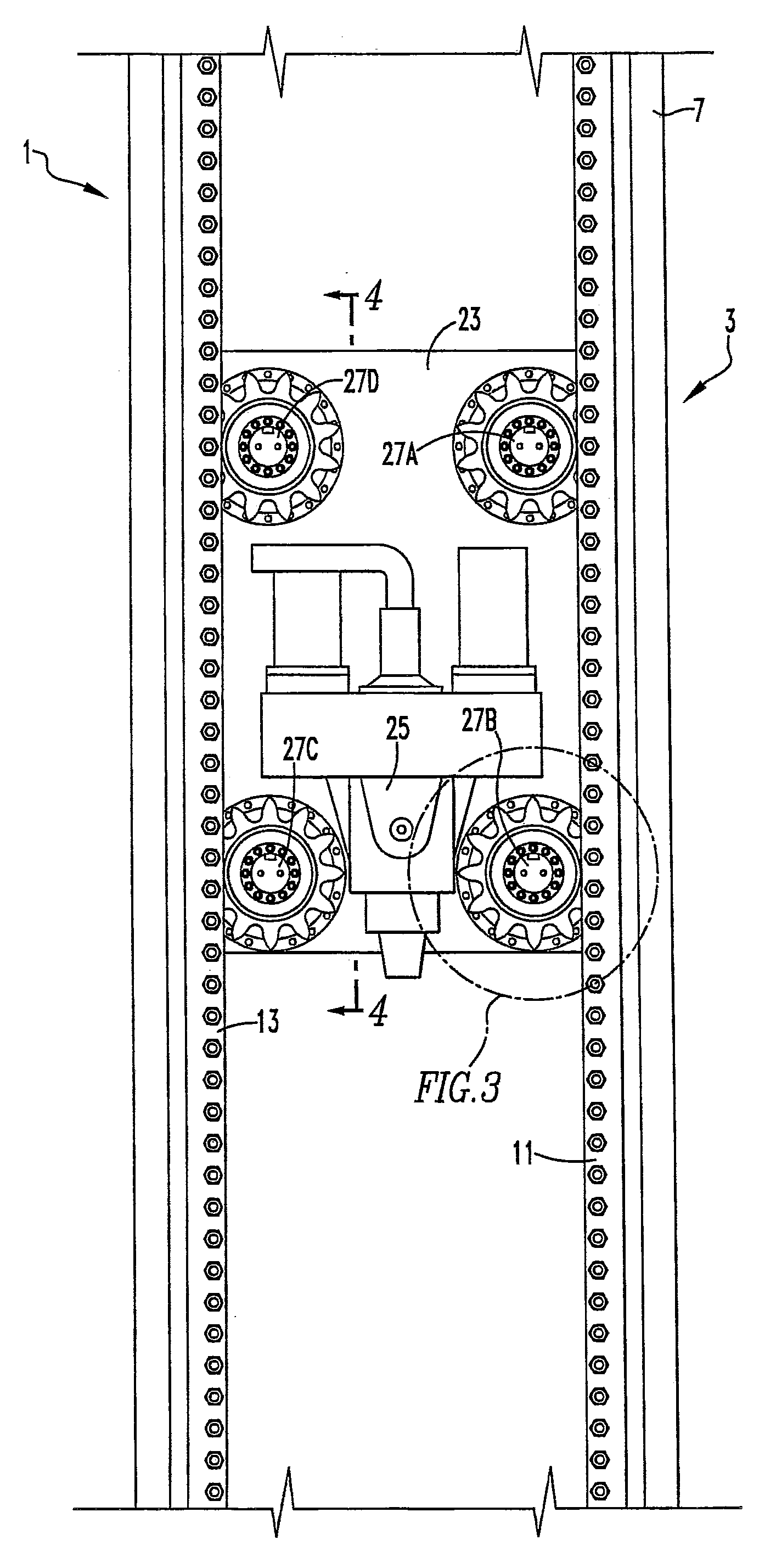
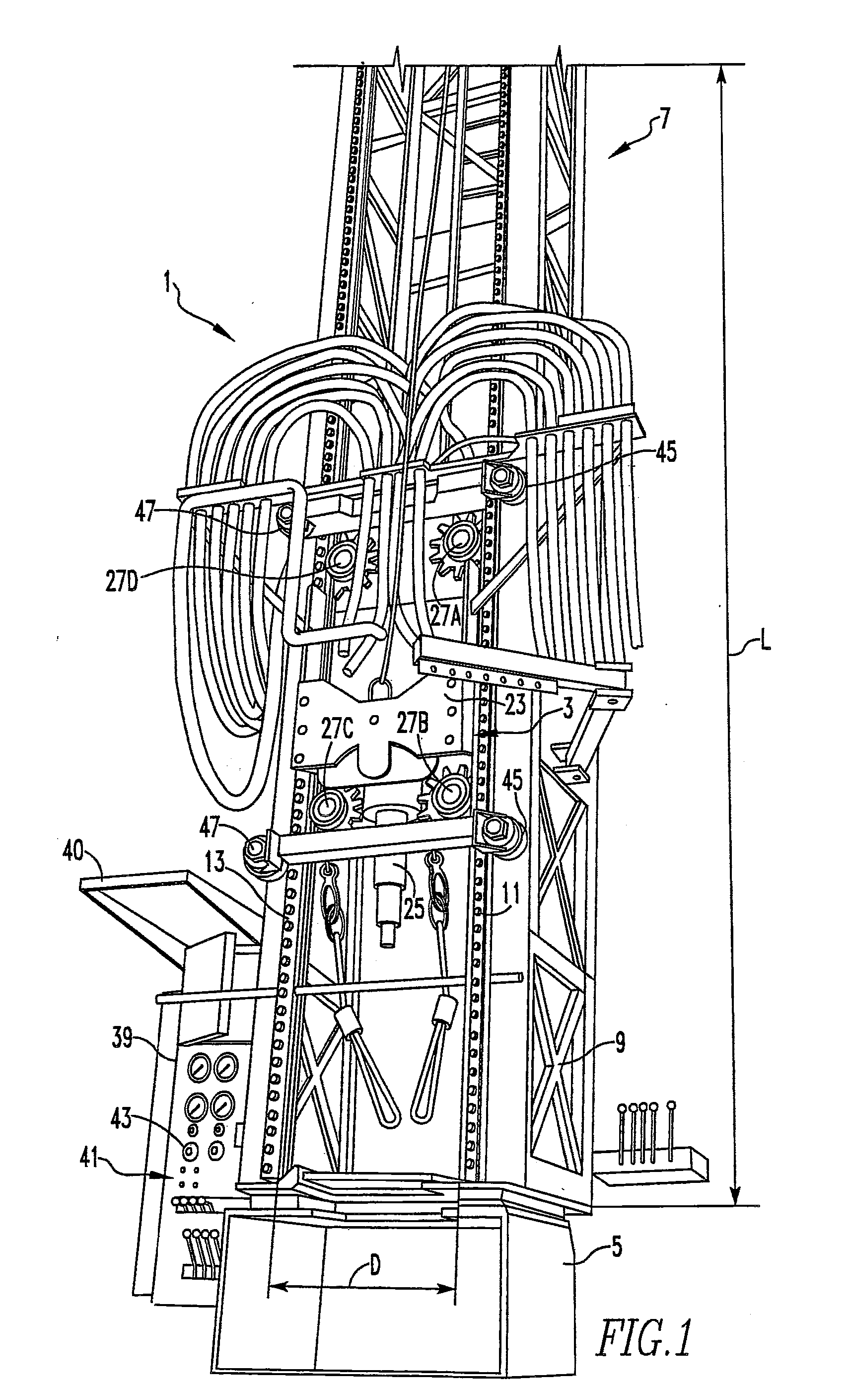
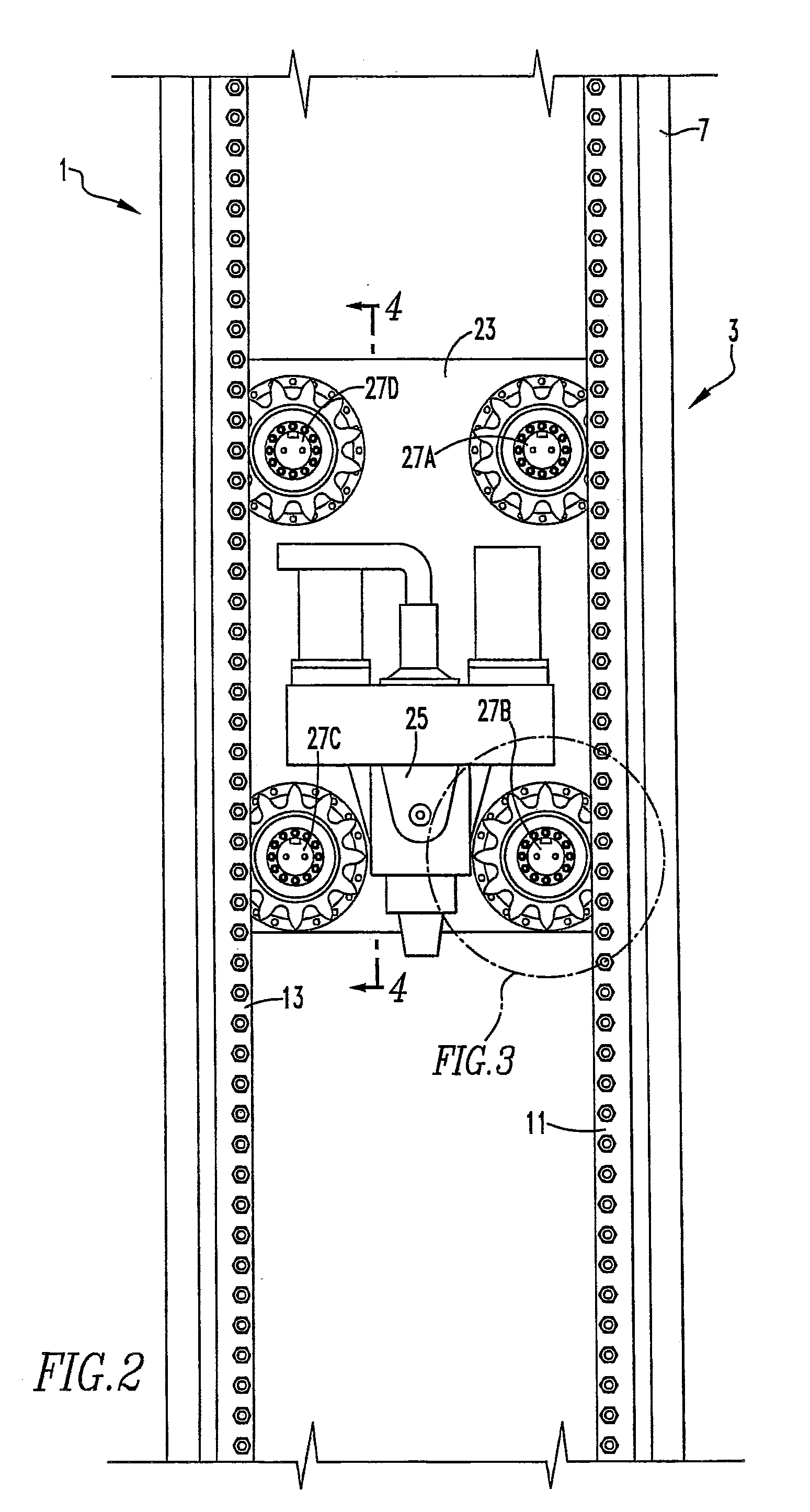
[0029]With reference to FIG. 1, a drilling rig, denoted generally as reference numeral 1, that includes a highly controllable top drive carriage assembly 3 is illustrated. Drilling rig 1 may be used for vertical drilling, horizontal drilling, combination verti...


PUM


Abstract

A drilling rig includes a mast base and a mast having a structural frame extending from the mast base. The structural frame includes a first track extending along the length of the structural frame and a second track extending along the length of the structural frame spaced from and parallel to the first track. The drilling rig also includes a top drive carriage assembly having at least one sprocket arrangement operatively engaged with one of the first track and the second track. The first track and the second track each include a plurality of bushings equally spaced apart and attached to spaced apart track plates. The at least one sprocket arrangement has a plurality of teeth configured to operatively engage the plurality of bushings such that the top drive carriage assembly moves along the length of the structural frame of the mast.

Description

CROSS REFERENCE TO RELATED APPLICATIONS[0001]This application claims the benefit of U.S. Provisional Patent Application No. 61 / 148,582 entitled “Track and Sprocket Drive for Drilling” filed Jan. 30, 2009, which is hereby incorporated by reference in its entirety.BACKGROUND OF THE INVENTION[0002]1. Field of the Invention[0003]The present invention relates, in general, to a drilling rig primarily for use in gas drilling and, more particularly, to a drive mechanism for a carriage of the drilling rig.[0004]2. Description of Related Art[0005]A vertical drilling rig is commonly used in oil, gas, and coal bed methane well drilling. Conventional vertical drilling rigs use heavy drill pipe and / or drill collars in order to exert downward force on the drill bit as it enters the earth's surface and begins the well bore.[0006]Vertically drilling an oil or gas well begins with the step of positioning a drill string terminating with a drill bit and rotating the drill string such that the drill bit...

Claims


Application Information

Patent Timeline
Patent Type & Authority Applications(United States)
IPC IPC(8): E21B3/00
CPCE21B19/083
Inventor RIDDLE, WESLEY C.BARNETT, RYAN A.
Owner TARGET DRILLING
Why Eureka
Eureka Blog
Learn More