
Three dimensional back projection method and an X-ray CT apparatus

a back projection method and a technology of computed tomography, applied in tomography, instruments, nuclear engineering, etc., can solve the problems of reducing the amount the need for at least 256 fft operations for every view, etc., and reducing the amount of computation for cone beam reconstruction. , the effect of significant reduction of the amount of fft computation in filtering

Inactive Publication Date: 2005-03-08
GE MEDICAL SYST GLOBAL TECH CO LLC
View PDF8 Cites 21 Cited by
  • Summary
  • Abstract
  • Description
  • Claims
  • Application Information

AI Technical Summary

Benefits of technology

[0009]The object of the present invention is therefore to provide three dimensional back projection method and an X-ray CT apparatus allowing the operation to be decreased, in the so-called cone beam reconstruction.

Problems solved by technology

The raw data obtained by using such a multidetector may have a huge data size, causing a problem that the FFT operation in the filtering may become huge.
For example, in case of a multidetector having 256 detector arrays, there is a problem that at least 256 FFT operations are needed for every view.

Method used


Image

  • Three dimensional back projection method and an X-ray CT apparatus
  • Three dimensional back projection method and an X-ray CT apparatus
  • Three dimensional back projection method and an X-ray CT apparatus

Examples


seventh embodiment

[0104]FIG. 32 shows a schematic flow diagram of the operation of X-ray CT apparatus according to a

[0105]FIG. 33 shows a schematic diagram of the appropriate number of lines.

[0106]FIG. 34 shows a schematic diagram of too much inferior number of lines.

[0107]FIG. 35 shows a schematic diagram of excessively superior number of lines.

[0108]FIG. 36 shows a schematic diagram of appropriate number of lines.

[0109]FIG. 37 shows a schematic diagram illustrating the relationship between the distance and the number of lines for standard image quality.

[0110]FIG. 38 shows a schematic diagram illustrating the relationship between the distance and the number of lines for lower image quality.

[0111]FIG. 39 shows a schematic diagram illustrating the relationship between the distance and the number of lines for higher image quality.

eighth embodiment

[0112]FIG. 40 shows a schematic flow diagram of the operation of X-ray CT apparatus according to an

[0113]FIG. 41 shows a schematic diagram of the appropriate number of lines.

[0114]FIG. 42 shows a schematic diagram of the appropriate number of lines.

[0115]FIG. 43 shows a schematic diagram illustrating the relationship between the view and the number of lines.

DETAILED DESCRIPTION OF THE INVENTION

[0116]The present invention will be described hereinbelow in greater details with reference to embodiments illustrated in the accompanying drawings.

first embodiment

[0117

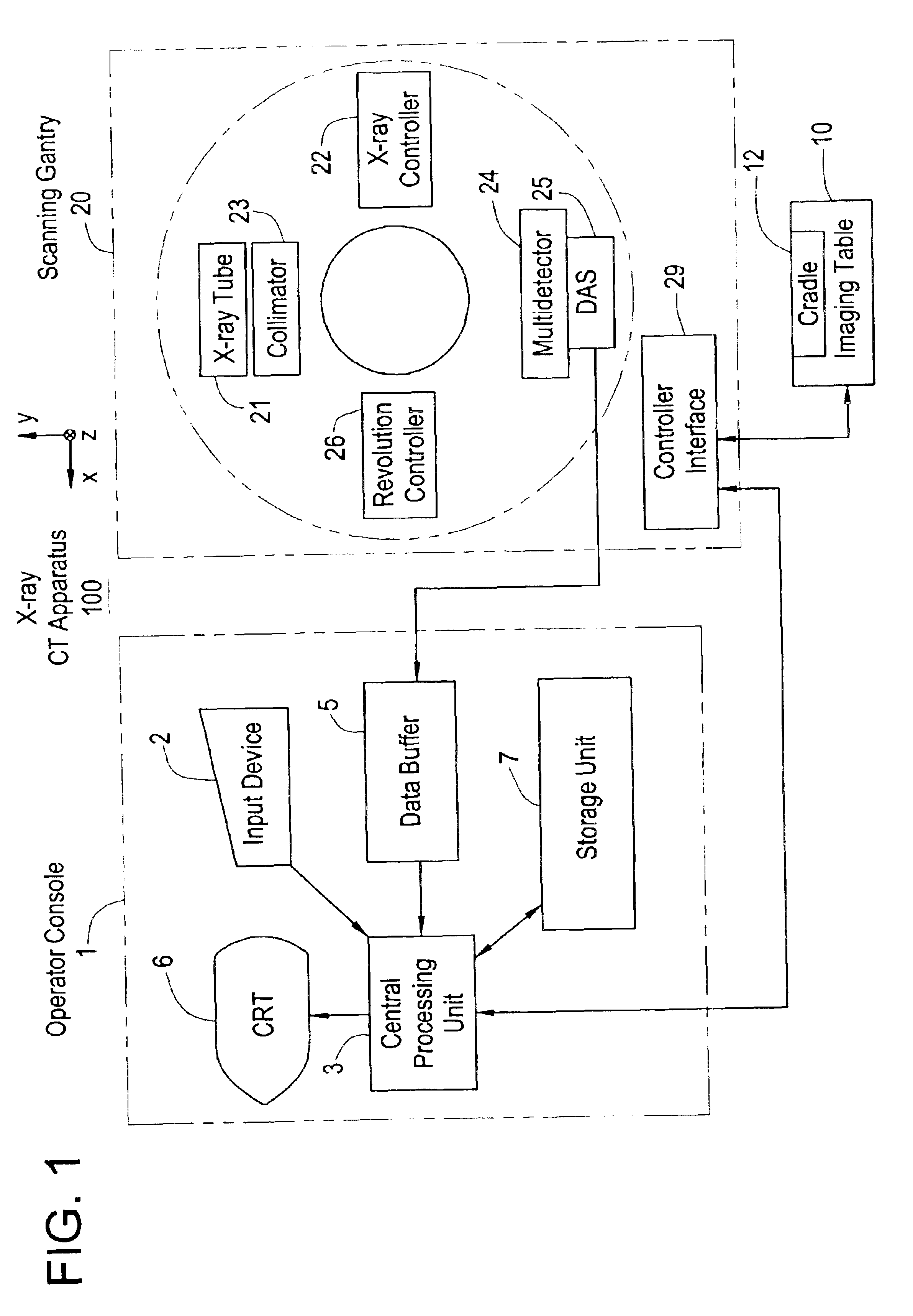
[0118]FIG. 1 shows a schematic block diagram of an X-ray CT apparatus according to a first embodiment of the present invention.

[0119]The X-ray CT apparatus 100 has an operator console 1, an imaging table 10, and a scanning gantry 20.

[0120]The operator console 1 includes an input device 2 for accepting input from an operator, a central processing unit 3 for executing three dimensional back projection process according to the present invention, a data buffer 5 for storing projection data obtained from the scanning gantry 20, a CRT 6 for displaying a CT image reconstructed from the projection data, and a storage unit 7 for storing such programs, data, as well as X-ray CT images.

[0121]The imaging table 10 includes a cradle 12 for carrying in and out the object to be imaged into and out of the bore (central void) of the scanning gantry 20. The cradle 12 may be driven by a motor incorporated in the imaging table 10.

[0122]The scanning gantry 20 includes an X-ray tube 21, an X-ray cont...


PUM


Abstract

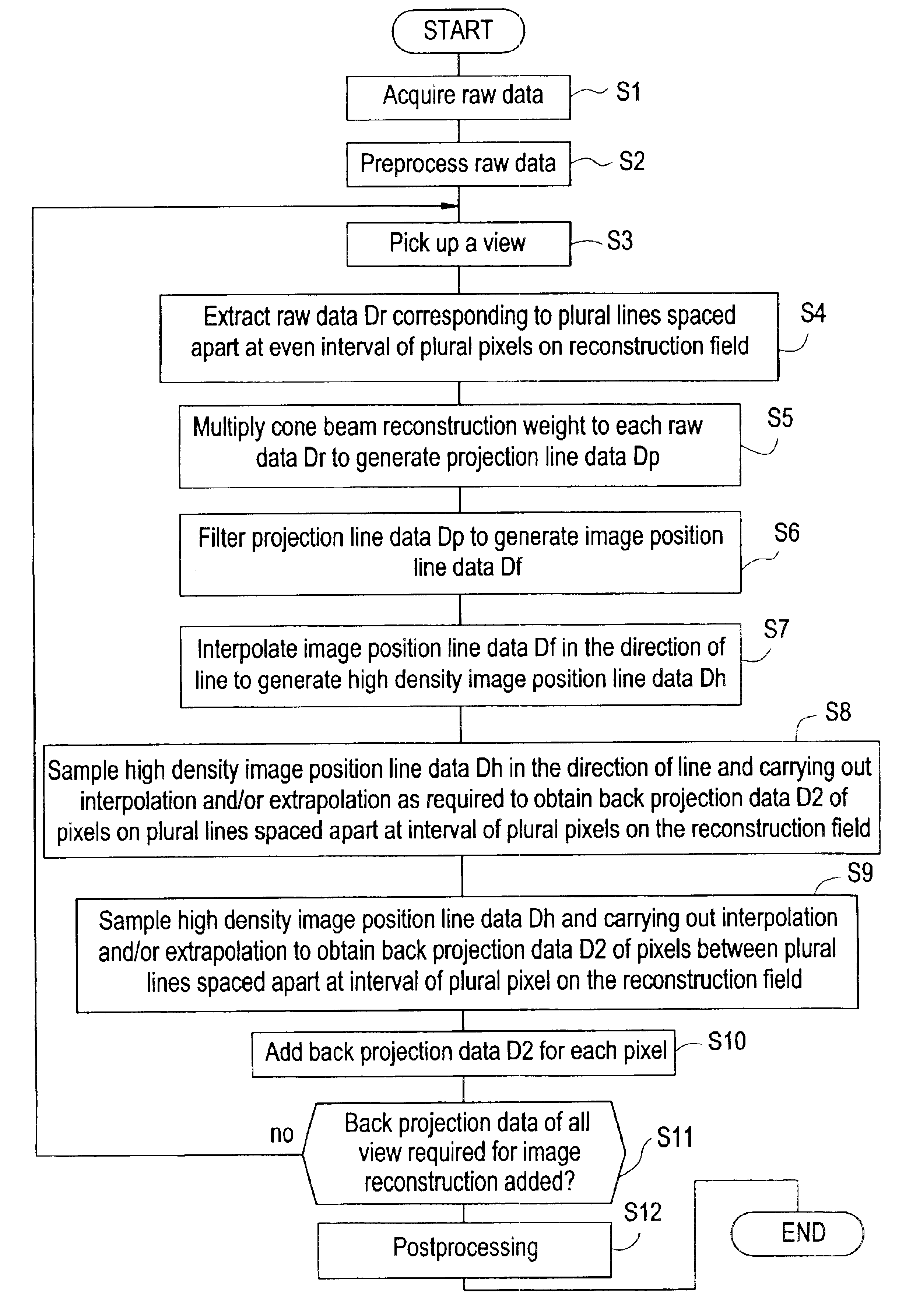
In order to reduce the amount of computation in the cone beam reconstruction, the invention provides, from within raw data acquired using a multidetector, extracting raw data Dr corresponding to plural lines on reconstruction field (S4), generating projection line data (S5) by multiplying raw data with cone beam reconstruction weight, filtering projection line data to generate image positional line data Df (S6), determining back projection pixel data (S7, S8, S9) of each pixel on the reconstruction field based on the image positional line data, adding, for each pixel, back projection pixel data of all views used for the image reconstruction to determine back projection data (S10, S11). The number of lines may be variable in compliance with a desired image quality.

Description

CROSS REFERENCE TO RELATED APPLICATIONS[0002]This application claims the benefit of Japanese Application No. 2002-147231 filed May 22, 2002, and Japanese Application No. 2002-322756 filed Nov. 6, 2002.BACKGROUND OF THE INVENTION[0003]The present invention is directed to three dimensional back projection method and an X-ray CT (computed tomography) apparatus, more specifically to three dimensional back projection method and an X-ray CT apparatus allowing the computation to be decreased by the image reconstruction based on the projection data obtained by the axial scan or helical scan using a multidetector (referred to as “cone beam reconstruction”).[0004]Current mainstream X-ray CT apparatuses uses filtered back projection scheme for reconstruction of a CT image through data capturing, preprocessing, filtering, back projecting and postprocessing.[0005]In the filtering, FFT operation is performed on the raw data, which is then multiplied by a reconstruction function in a frequency dom...

Claims


Application Information

Patent Timeline
IPC IPC(8): G06T11/00A61B6/03
CPCG06T11/005G06T11/006Y10S378/901A61B6/027G06T2211/421A61B6/03
Inventor HAGIWARA, AKIRA
Owner GE MEDICAL SYST GLOBAL TECH CO LLC
Learn More