Optical taps formed using fiber gratings

a fiber grating and optical tap technology, applied in the field of optical taps, can solve the problems of polarization-dependent problems and undesirable polarization effects, and achieve the effect of eliminating any polarization-dependent variations in the propagating optical signal

Inactive Publication Date: 2005-03-08
FURAKAWA ELECTRIC NORTH AMERICA INC
View PDF6 Cites 44 Cited by
  • Summary
  • Abstract
  • Description
  • Claims
  • Application Information

AI Technical Summary

Benefits of technology

[0009]In accordance with the present invention, an optical tap comprises a pair of grating structures, disposed in a contiguous relation along the core region of an optical waveguide (e.g., fiber). The gratings exhibit a relatively large blaze angle (e.g., approximately 45°), where polarization-dependent problems are overcome by disposing the pair of gratings in an orthogonal orientation such that the out-coupled

Problems solved by technology

The tap of the Meltz et al. patent exhibits shortcomings in terms of, for example, the relatively large (e.g., greater than 22°) blaze angle that is required to achieve the desired redirection of the light guided in the fiber core to light in space outside of the fiber, the arrangement is subject to undesirable polarization effects, i.e., the fraction of light that is

Method used


Image

  • Optical taps formed using fiber gratings
  • Optical taps formed using fiber gratings
  • Optical taps formed using fiber gratings

Examples


Embodiment Construction

polarization-insensitive tap of the present invention with an in-line all-fiber polarimeter, the tap used to measure the output power from the polarimeter;

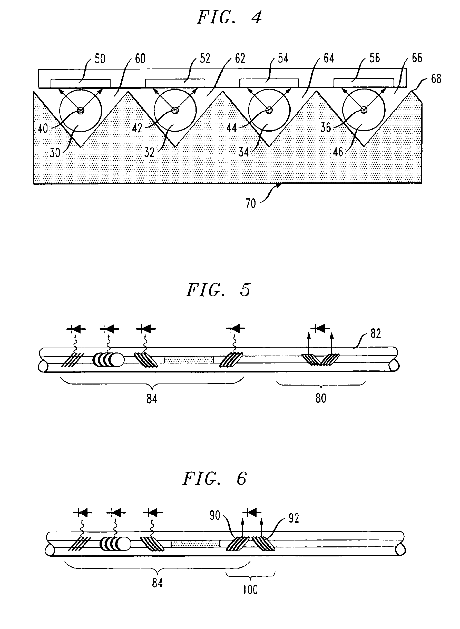
[0018]FIG. 6 contains an alternative embodiment of the combination of a polarimeter and an optical tap, where the final grating in the polarimeter is used as one of the gratings in the optical tap; and

[0019]FIG. 7 illustrates an optical tap of the present invention and an associated shaped reflector used to redirect the out-coupled light from the pair of fiber gratings.

DETAILED DESCRIPTION

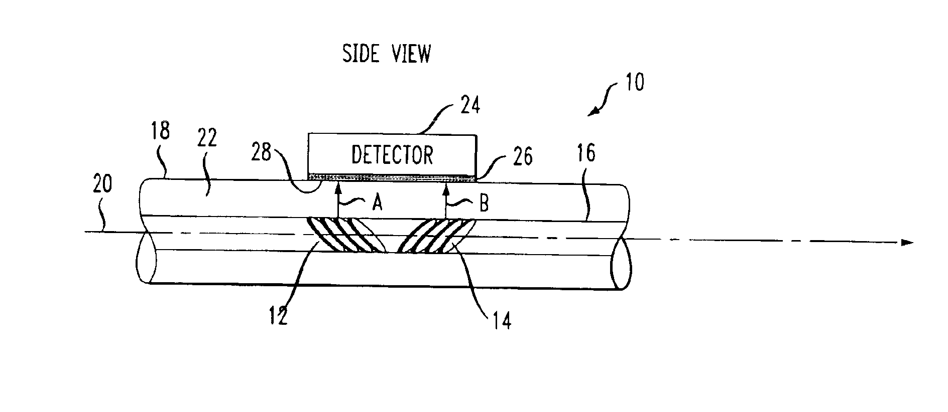
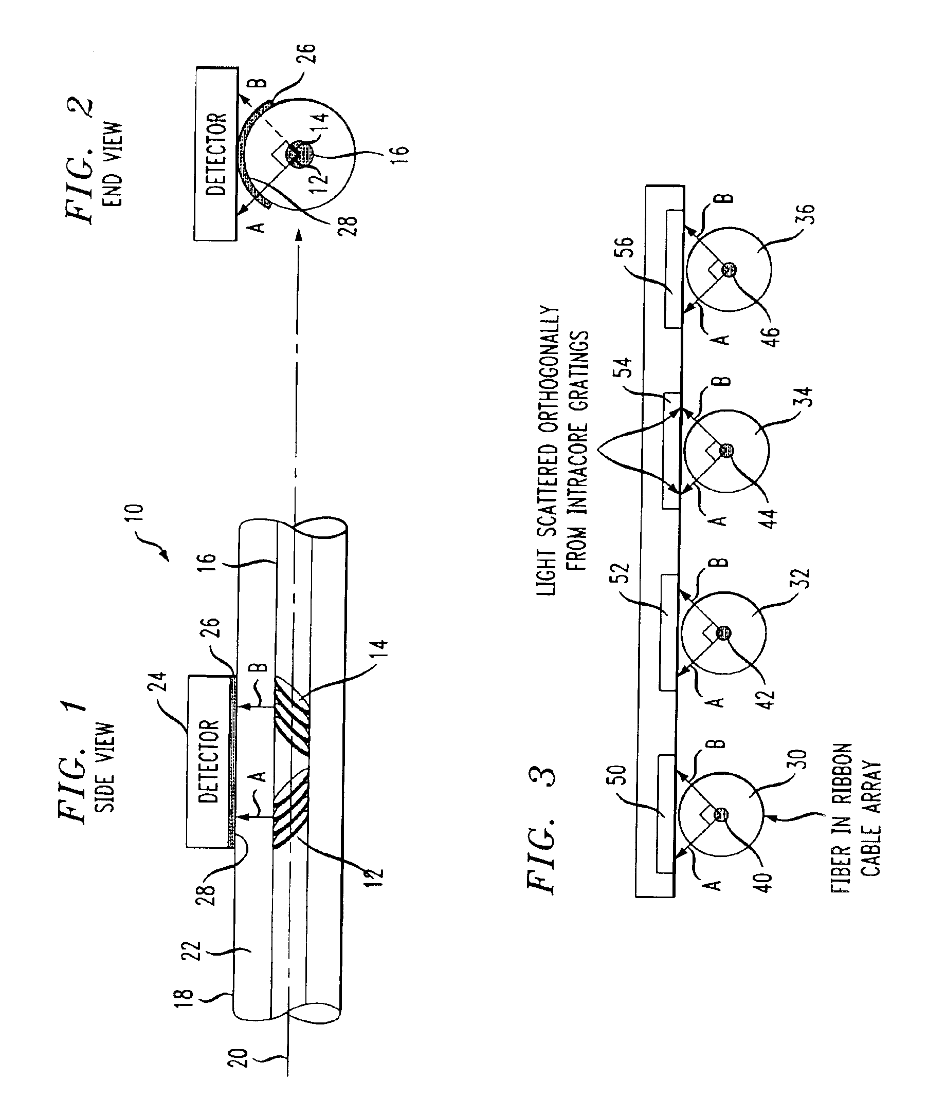
[0020]When the period of a fiber grating is adjusted so as to couple core guided light into light propagating approximately orthogonally through the fiber (that is, through the cladding so as to exit along the side of the fiber), the tilted grating will scatter the light in a highly polarization sensitive and highly directional manner. Importantly, the scattering is extremely broadband, since the orthogonally scattered light has a very small inte...


PUM


Abstract

A matched pair of tilted gratings may be formed in a section of optical fiber (or waveguide) and used as a “tap” to measure the power of an optical signal passing through the fiber. By using a pair of highly-tilted gratings (e.g., tilted at an angle of 45° with respect to the optical axis) and orienting the gratings to be orthogonal with respect to one another (i.e., azimuthal orthogonality around the fiber axis), a pair of orthogonally polarized beams will be out-coupled from the propagating signal. Since the pair of beams are orthogonal, their sum can be made insensitive to variations in polarization of the optical signal propagating along the fiber.

Description

CROSS-REFERENCE TO RELATED APPLICATION[0002]This application claims the benefit of U.S. Provisional Application No. 60 / 364,875, filed Mar. 15, 2002.TECHNICAL FIELD[0003]The present invention relates to an optical tap and, more particularly, to a fiber-based tap formed by using a matched pair of fiber gratings.BACKGROUND OF THE INVENTION[0004]There are already known various constructions of optical waveguides, including optical fibers, that are provided with embedded gratings which are used for removing light at various locations along the extent of the waveguide (i.e., an “optical tap”). In particular, it is possible to convert a guided mode wave in an optical fiber into a leaky mode exiting the waveguide by forming a grating of appropriate periodicity in at least the core region of the waveguide or fiber, thus directing the radiation out of the optical axis. In many optical systems, an optical tap is useful in capturing and monitoring the signal passing through the optical waveguid...

Claims


Application Information

Patent Timeline
IPC IPC(8): G01J1/42G01J1/04G02B6/28G02B6/02G02B6/34
CPCG01J1/04G01J1/0407G01J1/0422G01J1/0425G02B6/4215G02B6/02085G02B6/02109G02B6/2852G01J1/4257G01J1/0209G02B6/29323
Inventor WESTBROOK, PAUL
Owner FURAKAWA ELECTRIC NORTH AMERICA INC
Why Eureka
Try Eureka