
Fiber optic device with enhanced resistance to environmental conditions and method

a technology of environmental conditions and fiber optic devices, applied in the field of fiber optic device fabrication, can solve the problems of couplers that cannot meet the performance specifications assigned to them, couplers that cannot be used in packaging, and may exhibit a gradual drift in insertion loss, etc., and achieve the effect of avoiding high excess loss

Inactive Publication Date: 2005-03-08
GOI ACQUISITION
View PDF45 Cites 3 Cited by
  • Summary
  • Abstract
  • Description
  • Claims
  • Application Information

AI Technical Summary

Benefits of technology

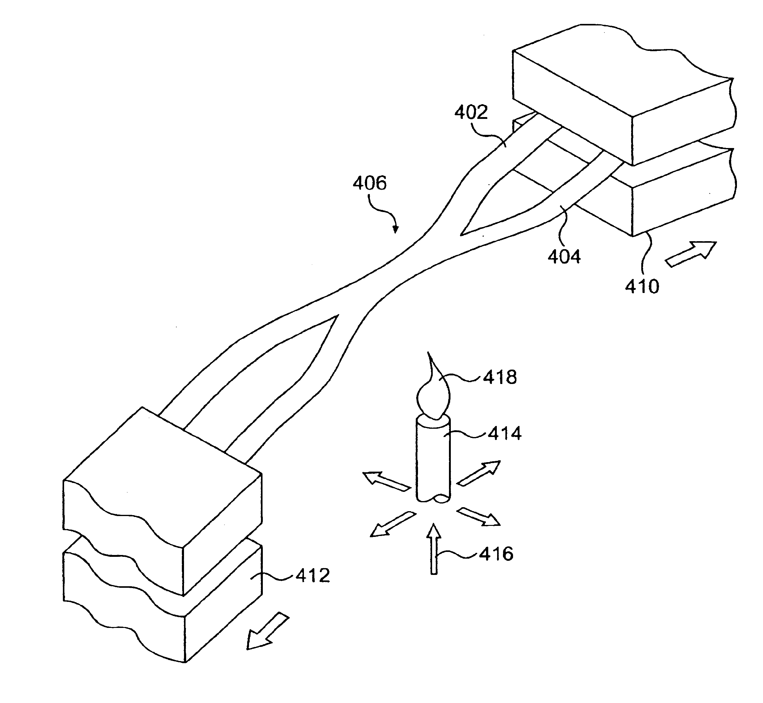
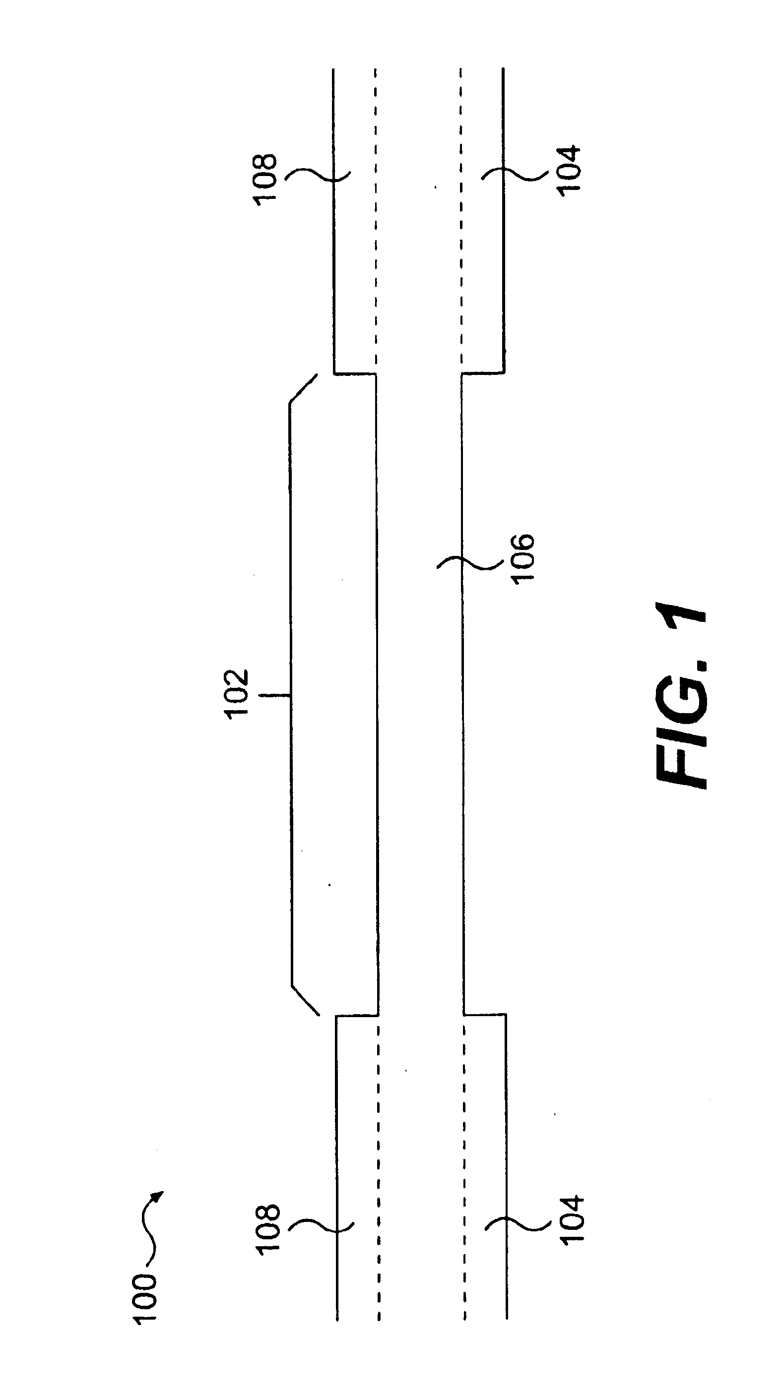
In another embodiment, the invention provides an optic device including at least two optic fibers having respective longitudinal segments, in which the longitudinal segments are fused together by a deuterium process. The optic device exhibits no high excess loss in a portion of the CWDM spectrum.

Problems solved by technology

Fiber optic couplers exposed to such conditions may exhibit a gradual drift in insertion loss.
Eventually, this drift will cause a coupler to fail to meet its assigned performance specifications.
These types of packaging have not proved successful in preventing the aforementioned problem.
However, these attempts have also failed.
Such approaches are deficient because it has been discovered that the introduction of water and water related species during fabrication is not a major cause of long-term drift of optical properties under damp heat accelerated aging conditions.

Method used


Image

  • Fiber optic device with enhanced resistance to environmental conditions and method
  • Fiber optic device with enhanced resistance to environmental conditions and method
  • Fiber optic device with enhanced resistance to environmental conditions and method

Examples


example 1

Deuterium Passivation Damp Heat Aging Experiment

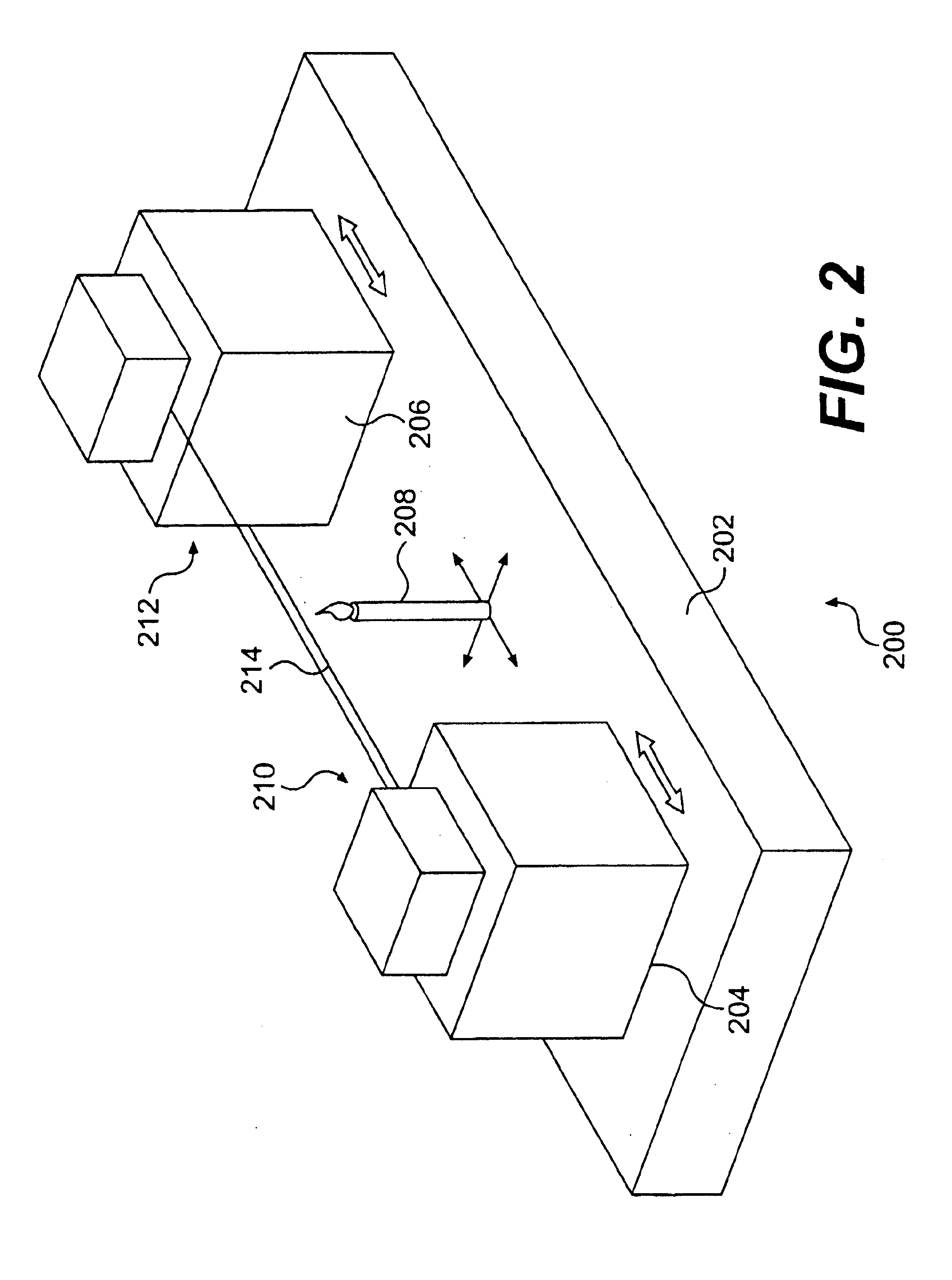
Twenty-five (25) 50% wavelength flattened optic couplers (WFC) were manufactured using a deuterium gas fueled heating source, with the goal of attaining passivation (i.e., to treat in order to reduce the chemical reactivity of its surface) of the couplers to damp heat aging. These deuterium couplers, along with eleven (11) 50% WFCs produced using the standard “hydrogen heating” method, were aged at 85° C. and 85% relative humidity (RH) for approximately 2000 hours and 1265 hours, respectively. The eleven standard couplers act as a control group.

Optic Fiber Parameters for 50% WFC Deuterium CouplerD2 flow rate: 215 sccmO2 flow rate: 0 sccmStage separation: 40 mmPre-taper torch velocity: 22 mm / minPre-taper flame brush width: 11 mmPre-taper right stage velocity: 2.75Pull torch-velocity: 36 mm / minPull flame brush width: 6.5 mmPull left stage velocity: 2.5 mm / minPull right stage velocity: 2.5 mm / minPull after stop jump: 3.5%Torch height: 10....


PUM

PropertyMeasurementUnit
Temperatureaaaaaaaaaa
Fractionaaaaaaaaaa
Timeaaaaaaaaaa

Abstract

A method for producing fiber optic devices having improved intrinsic resistance to external environmental conditions and a fiber optic device made my the method are disclosed. The fabrication method produces an optic device that is treated with deuterium. The method includes a step for treating and / or making optical devices in the presence of a flame produced by the combustion of deuterium gas or a mixture including deuterium.

Description

FIELD OF THE INVENTIONThe present invention relates to fabrication of fiber optic devices, and more particularly to a fabrication method that produces fiber optic devices having improved intrinsic resistance to external environmental conditions.BACKGROUND OF THE INVENTIONThe widespread and global deployment of fiber optic networks and systems mandates that fiber optic devices and components operate reliably over long periods of time. This mandate imposes stringent performance requirements on various fiber optic devices and components that are used in such networks and systems. In this respect, since fiber optic devices and components are expected to operate reliably for decades or more, prior to qualification for use, such components are typically subjected to an array of mechanical and environmental tests that are designed to measure their long term reliability.Guarantees of long term performance become especially crucial in application where the cost of failure is very high (e.g.,...

Claims


Application Information

Patent Timeline
IPC IPC(8): C03B37/10C03C13/04C03C25/60C03C13/00C03B37/15G02B6/28G02B6/287
CPCC03B37/15G02B6/2835C03C25/607C03C13/047C03B2201/22
Inventor TALLENT, JACK R.HOFFMAN, III, ARTHUR J.PILEVAR, SAEED
Owner GOI ACQUISITION
Learn More