Methods and apparatus for reducing the shrinkage of an optical disc's clamp area and the resulting optical disc

a technology of optical discs and clamps, applied in the field of single-substrat optical discs, can solve the problems of reducing the efficiency of the disc manufacturing process, reducing the effect of negative effects on the manufacture and performance of the disc, and reducing the amount of material needed. , the effect of reducing the amount of material needed

Inactive Publication Date: 2005-03-08
WEA MANUFACTURING
View PDF19 Cites 39 Cited by
  • Summary
  • Abstract
  • Description
  • Claims
  • Application Information

AI Technical Summary

Benefits of technology

In accordance with the principles of the present invention, the above-described warping phenomenon and its related negative effects on the manufacture and performance of the disc are reduced by altering the design of the hub structure, thereby decreasing the amount of material necessary to emulate the thickness of a double-substrate disc. For example, the solid hub of the prior art, such as the hub shown in FIG. 1 and described in International Application WO 98 / 10418, may be replaced by one or more relatively small protrusions located in the clamp area of the disc. These protrusions may be of various shapes, for example, spokes, bumps or rings, and may vary in number, location, shape and size. In addition to reducing the shrinkage in the hub structure, this approach results in reduced manufacturing cost by allowing faster molding of the discs and decreasing the amount of material needed to form the disc's clamp area. Furthermore, the present invention allows the production of discs with a more aesthetically pleasing appearance.

Problems solved by technology

For example, when a disc is manufactured according to the design described above, the large amount of material used in forming the hub may cause the hub to shrink radially and vertically, pulling in material from other regions of the disc, including information-carrying regions.
This warping phenomenon may negatively affect the tilt, stress, birefringence and electrical properties of the disc.
Attempts at reducing this phenomenon, such as increasing cool-down time in the mold for each disc, reduce the efficiency of the disc manufacturing process.

Method used


Image

  • Methods and apparatus for reducing the shrinkage of an optical disc's clamp area and the resulting optical disc
  • Methods and apparatus for reducing the shrinkage of an optical disc's clamp area and the resulting optical disc
  • Methods and apparatus for reducing the shrinkage of an optical disc's clamp area and the resulting optical disc

Examples


Embodiment Construction

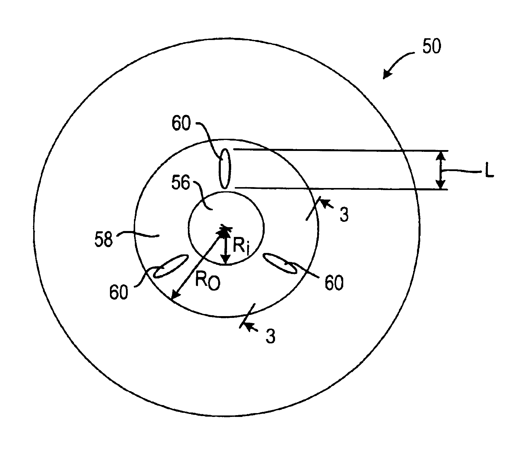
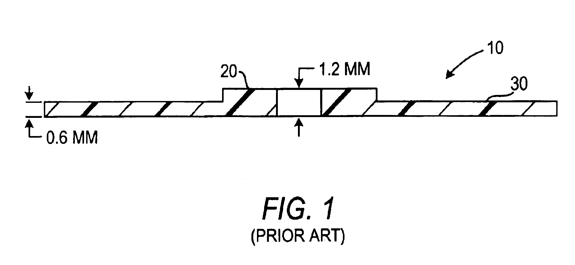
The invention comprises an optical disc 50 (FIGS. 2 and 3), such as an audio or video DVD, typically manufactured of plastic, one of the surfaces 52 (the upper surface in FIG. 2) of the disc having pits and lands representing data. The pits and lands are, of course, too small to be depicted in drawings having the scale employed herein. (Although “pits and lands” are generally referred to herein, it will be understood that the data recording technology may alternatively be (or may alternatively be referred to as) “bumps and lands.” The phrase “pits and lands” herein will be understood to be generic to both “pits and lands” and “bumps and lands.”) The objects of the present invention are accomplished by manufacturing a single-substrate optical disc 50 having one or more relatively small protrusions 60 in the clamp area.

As shown in FIGS. 2 and 3, one example of an optical disc 50 according to the present invention comprises a substantially transparent disc-shaped substrate 54, having o...


PUM

PropertyMeasurementUnit
heightaaaaaaaaaa
inner radiusaaaaaaaaaa

Abstract

An improved optical disc is provided that comprises a substantially transparent substrate, one surface of which carries optical data structures comprising pits and lands radially outward of a clamp area of the disc. In the clamp area a protrusion structure is provided above the first surface to create a clamp thickness greater than the thickness of the rest of the disc. In accordance with the principles of the present invention, only a portion of the clamp area is covered by the protrusions, which emulate a disc having a clamp area of greater thickness. In order to reduce warping caused by shrinkage of material added to the clamp area, the amount of material used to form the protrusions is less than 5% of the amount of material used to form the rest of the clamp area.

Description

BACKGROUND OF THE INVENTIONThis invention relates to single-substrate optical discs, such as single-substrate audio or video DVDs.Optical discs having pits and lands that form an optical track structure on one surface are known as single-substrate optical discs, while double-substrate optical discs, in which two single-substrate discs are bonded to each other back to back, are known as dual-substrate optical discs. When a dual-substrate disc is manufactured, the clamp area is characterized by the aggregate thickness of the two bonded substrates. (“Clamp area” is the area of a DVD that is covered or engaged by the clamp mechanism of the reproducing apparatus during play-back of the DVD. The word “area” is frequently used herein to refer to what is actually a three-dimensional portion or region of an optical disc. Thus the clamp area of a disc is not just a two-dimensional surface area, but also the thickness of the disc in that two-dimensional area. A certain volume, quantity, or amo...

Claims


Application Information

Patent Timeline
Patent Type & Authority Patents(United States)
IPC IPC(8): G11B23/00G11B7/24G11B7/26
CPCG11B23/0035G11B7/24003G11B7/24G11B7/26
Inventor MYRTLE, JAMES
Owner WEA MANUFACTURING
Why Eureka
Try Eureka