Method of making composite laminate automotive structures

a technology of automotive structure and composite laminate, which is applied in the direction of bumpers, doors, vehicular safety arrangments, etc., can solve the problems of increasing the weight of the part, increasing the difficulty of forming the part, and increasing the weight of the metal gauge, so as to achieve the effect of reducing cost and weight, and increasing compression resistan

Inactive Publication Date: 2005-03-15
HENKEL KGAA
View PDF61 Cites 31 Cited by
  • Summary
  • Abstract
  • Description
  • Claims
  • Application Information

AI Technical Summary

Benefits of technology

In still another aspect, the present invention provides a door beam or side impact beam for a motor vehicle door which provides increased compression resistance at minimal cost and weight. A local reinforcement is provided in the midspan of a steel shell. The l

Problems solved by technology

Although filling sections with plastic foam does significantly increase section stiffness (at least when high-density foams are utilized), they also increase mass and thus part weight, which, as stated, is an undesirable feature in automotive applications.
Moreover, although increasing the metal gauge of a section or adding localized metal reinforcements will increase stiffness, as the metal thickness increases, it is more difficult to form the part due to limitations

Method used


Image

  • Method of making composite laminate automotive structures
  • Method of making composite laminate automotive structures
  • Method of making composite laminate automotive structures

Examples


Embodiment Construction

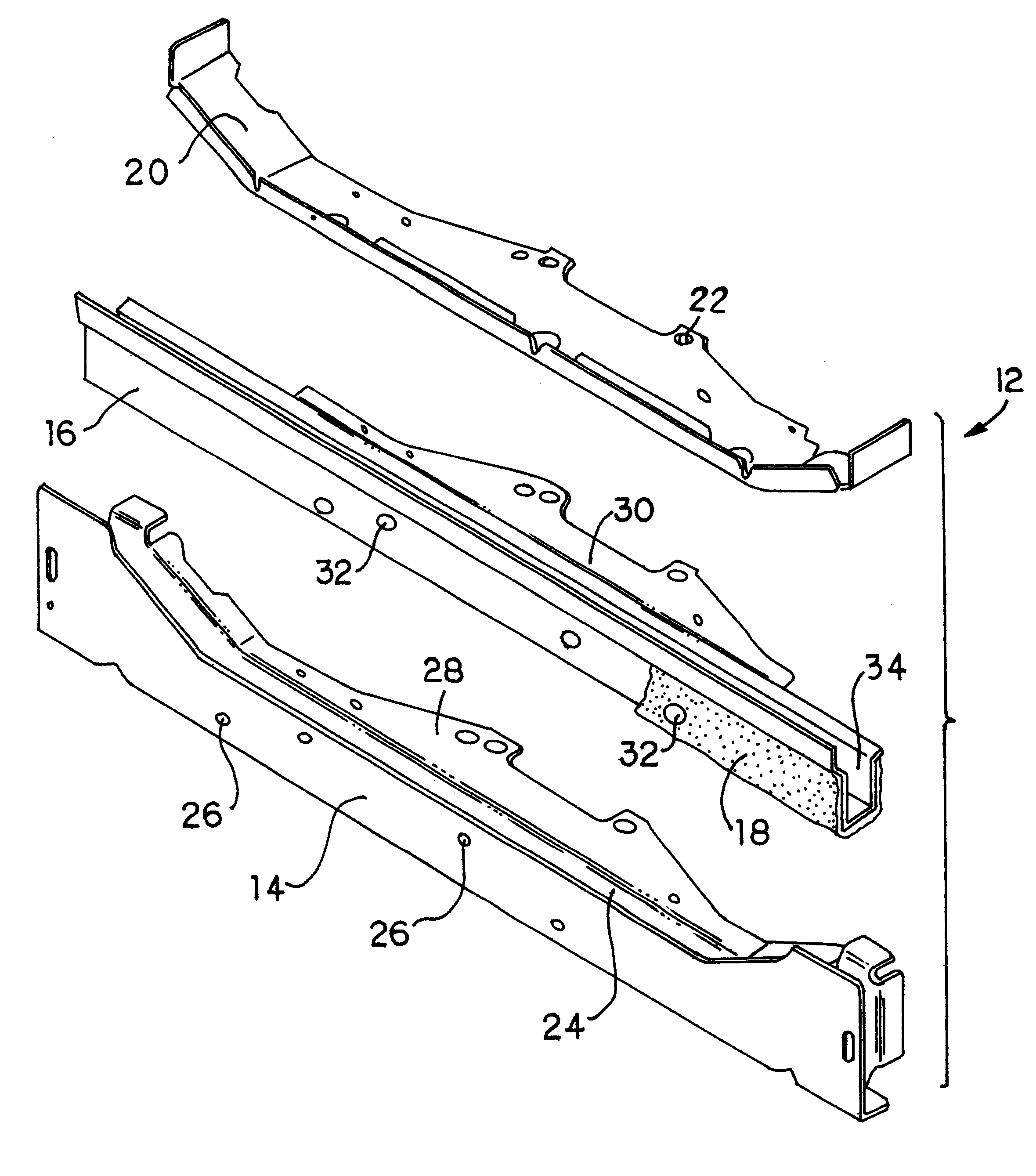
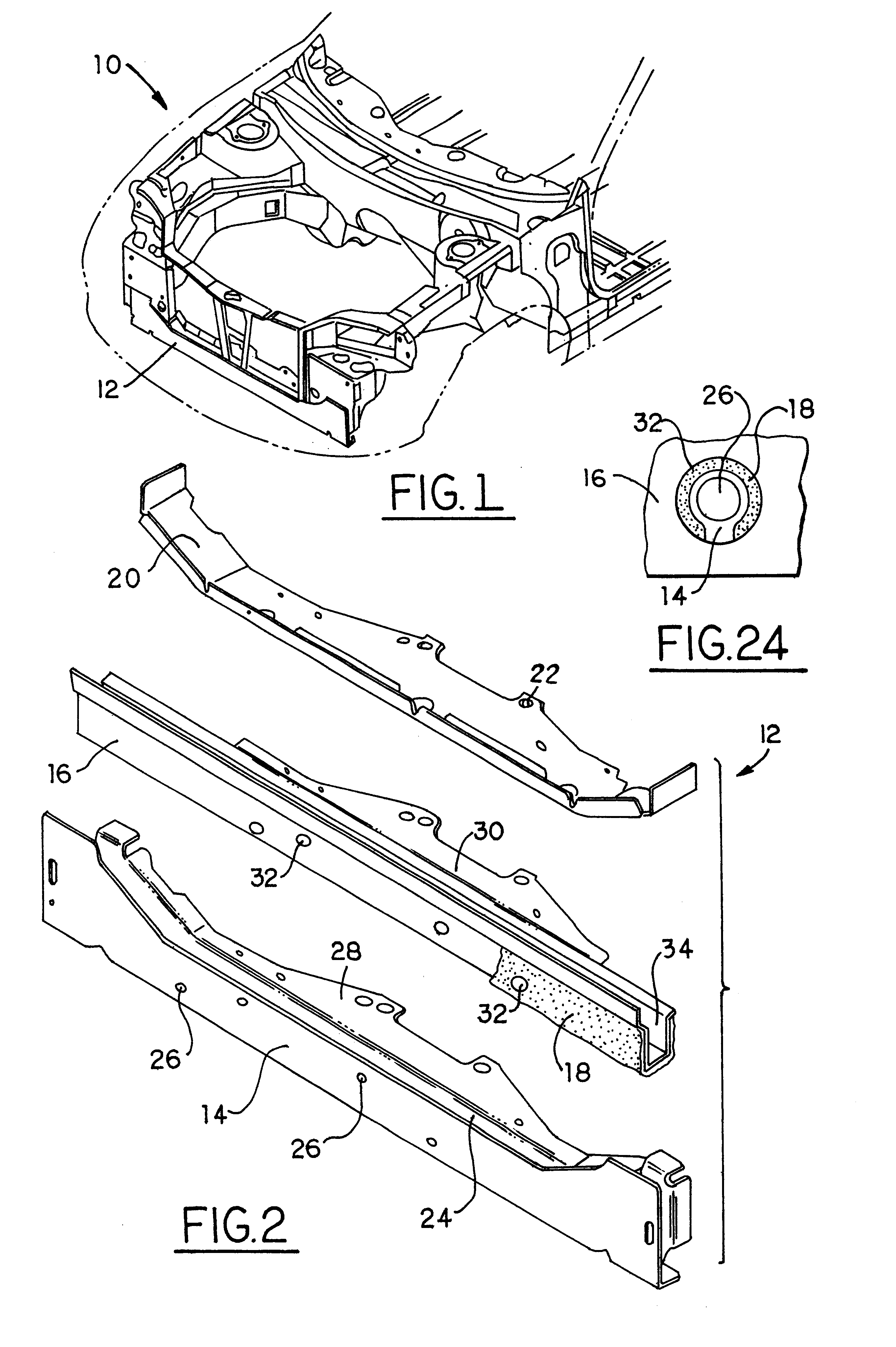
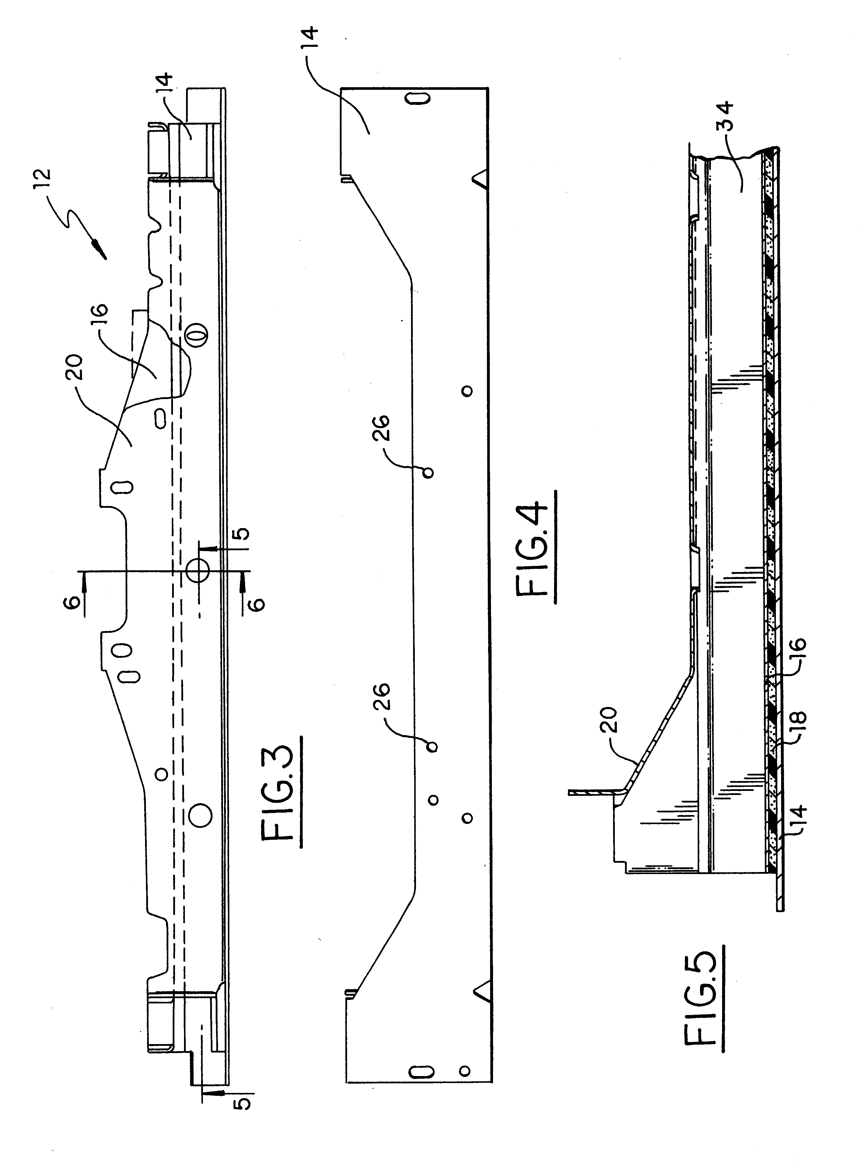
Referring now to FIG. 1 of the drawings, a motor vehicle 10 is shown with the engine removed and the body illustrated in phantom. Radiator support structure or beam 12 is mounted on the chassis and serves to support the vehicle radiator (not shown). In FIG. 2, radiator support beam 12 is illustrated in exploded view having outer shell or portion 14 which in this embodiment is a steel stamping. An inner tube, here shown as channel-shaped tube 16, is provided having a layer of resin-based material 18 applied to selected surfaces. Cap 20 is seen having a plurality of through-holes 22 and serves to enclose channel-shaped tube 16 within outer shell 14.

More specifically, and referring now of FIGS. 2 through 6 and 24, outer shell 14 defines a cavity or channel 24. A number of through-holes 26 are seen through which electric wiring (not shown) may extend. Outer shell 14 includes a laterally extending mounting bracket or plate portion 28 which is secured to components of the engine assembly....


PUM

PropertyMeasurementUnit
Lengthaaaaaaaaaa
Lengthaaaaaaaaaa
Lengthaaaaaaaaaa

Abstract

A structural member having at least two non-coplanar surfaces is reinforced by providing a drop in insert between the surfaces. The insert is a carrier having an expandable structural foam intimately bonded to the carrier. When the foam is expanded, the foam becomes intimately bonded to the surfaces of the structural member to reinforce the structural member.

Description

TECHNICAL FIELDThe present invention relates generally to automotive body structural members and, more specifically, relates to techniques for increasing strength and stiffness of automotive body structural members.BACKGROUND OF THE INVENTIONIn a number of applications, particularly in the automotive industry, it is important to provide high-strength structural members at the lowest possible mass. A number of composite materials have been proposed by others in the past for use in forming structural members, including exotic lightweight alloys, In the automotive industry, however, the need for mass reduction without sacrificing strength must be balanced against the cost of the product to the consumer. Thus, there is a need for maintaining or increasing the strength of structural members such as rockers, windshield, pillars, radiator support beams, drive shafts, side impact beams, and bumpers without significantly increasing materials and labor costs.The reinforcement of motor vehicle...

Claims


Application Information

Patent Timeline
IPC IPC(8): B29C44/02B29C44/12B60J5/04B62D25/00B62D29/00B62D25/08B60K17/22B60R19/18
CPCB29C44/1228B60J5/0447B60J5/0452B60K17/22B60R19/18B62D25/00B62D25/084B62D29/001B62D29/002B62D29/007B29C44/1242Y10T29/49622B60R2019/1813B60R2019/1846Y10T29/49616B29C44/14
Inventor WYCECH, JOSEPH S.
Owner HENKEL KGAA
Why Eureka
Try Eureka