
Forklift with transverse travel system

Inactive Publication Date: 2005-03-15
TCM
View PDF15 Cites 16 Cited by
  • Summary
  • Abstract
  • Description
  • Claims
  • Application Information

AI Technical Summary

Benefits of technology

The present invention has an object to provide a forklift with transverse travel system, in which front wheels and rear wheels can be steered straight sideways and the front-and-rear balance can be maintained properly.
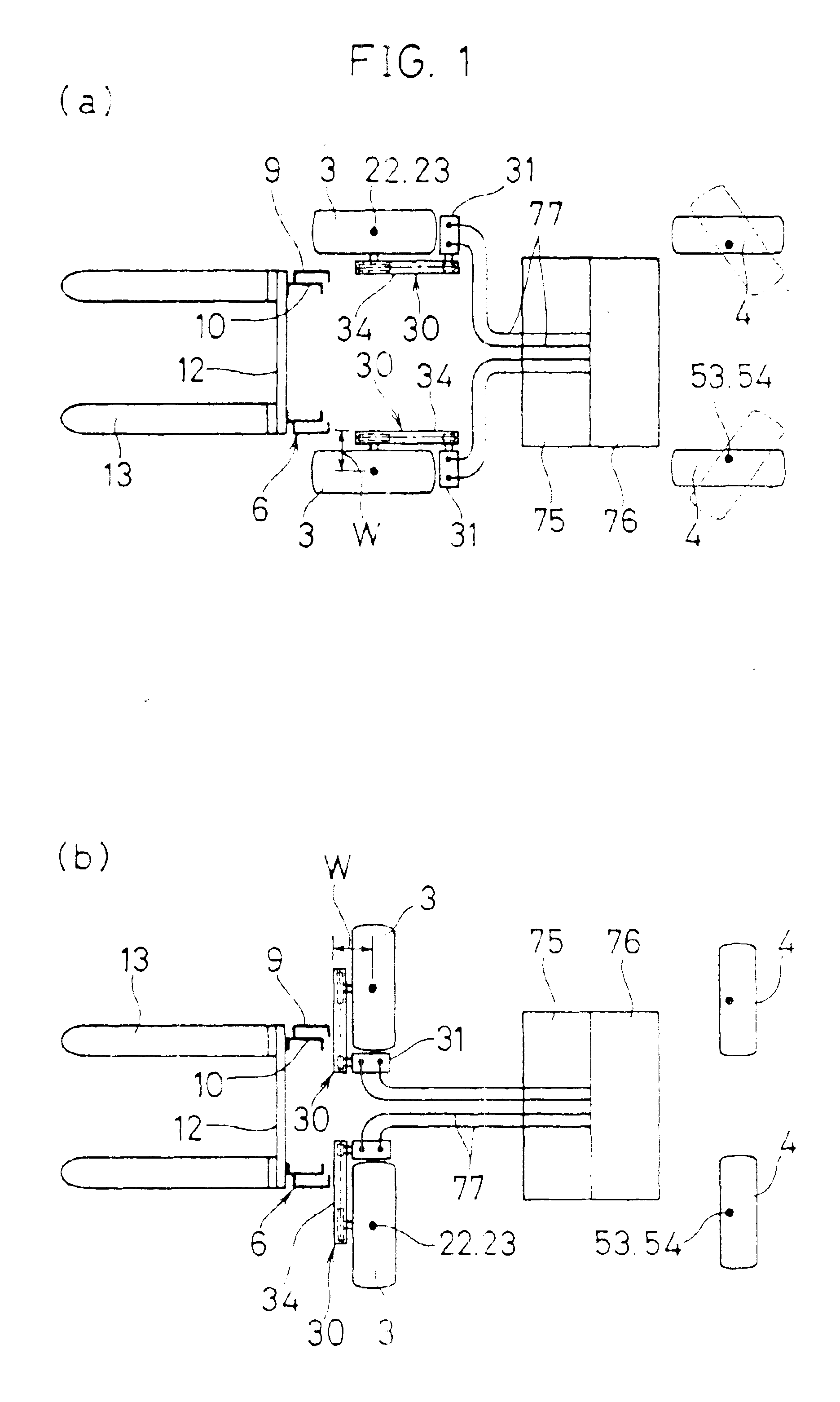
When changing from a normal travel operation to a transverse travel operation, for example, a lever-style transverse travel mode switch is operated to activated a turning means. Therefore, operating the turning means allows the front wheels to turn around the vertical axes, enabling steering of the front wheels by 90 degrees (straight sideways) in relation to the vehicle, thus the forklift can travel laterally to the right or the left after the front wheels are steered straight sideways.
Consequently, in the system allowing the front wheels to steer straight sideways, it becomes unnecessary to install the mast so forward as unnecessary. That is to say, the mast may be installed in the same manner as in a conventional non-laterally traveling forklifts, so that the front-and-rear balance of the forklift can be maintained satisfactorily without increasing the self-weight of the forklift.

Problems solved by technology

However, there are no counter balance type forklifts that can move sideways and function like a side forklift in addition to such tasks as generally required.
However, since the right and left frontwheels 3 are driven in common by a same travel drive system, the above mentioned conventional forklift 1 cannot effect straight-sideways steering of the front wheels, thus being unable to move laterally.

Method used


Image

  • Forklift with transverse travel system
  • Forklift with transverse travel system
  • Forklift with transverse travel system

Examples


Embodiment Construction

An embodiment of the present invention will be explained below using FIGS. 1 through 7. In these embodiments, components identical or almost identical to those of the conventional art (FIG. 8) are labeled with like reference symbols and detailed explanations thereof are omitted.

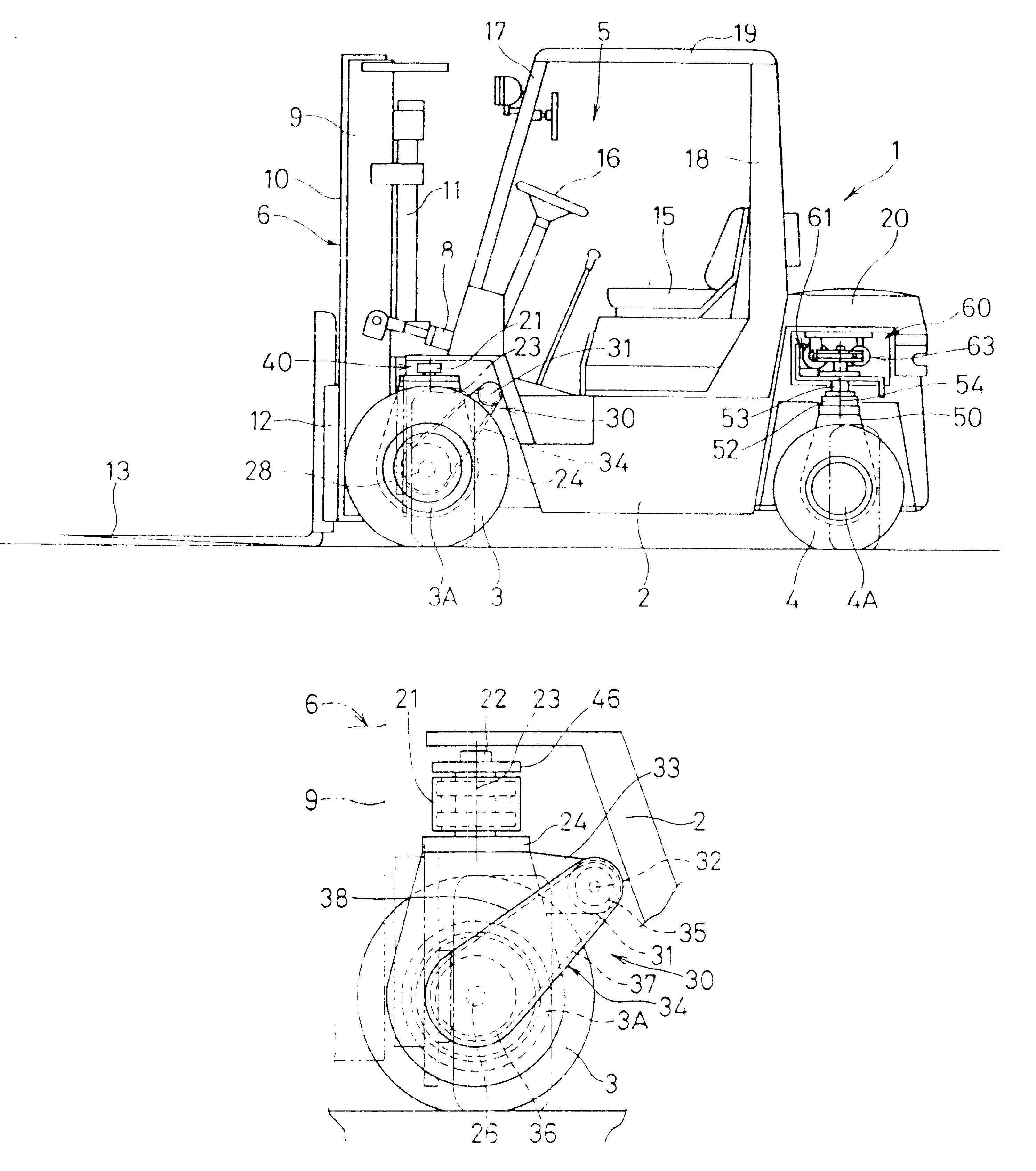
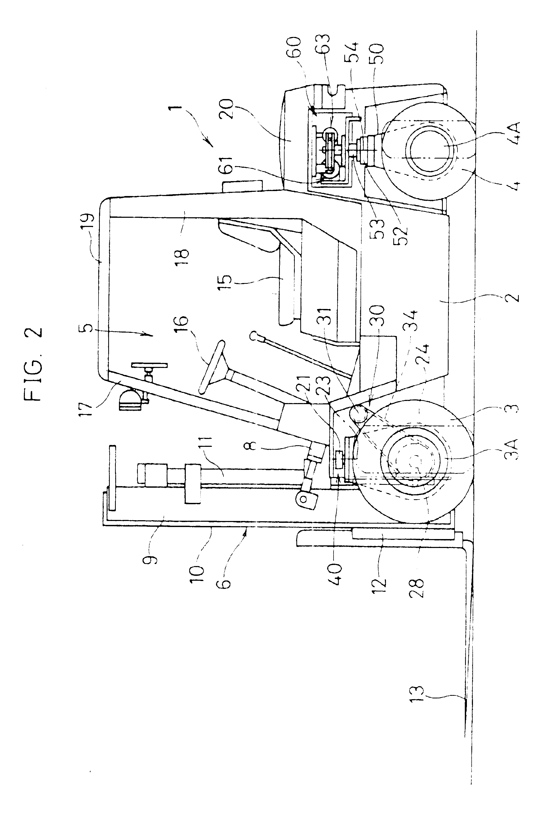
Reference symbol 1 shows a forklift, 2 a vehicle body, 3 a front wheel (drive wheel), 4 a rear wheel (steerable wheel), 5 a driver's seat, 6 a mast, 8 a tilt cylinder, 9 an outer frame, 10 an inner frame, 11 a lift cylinder, 12 a lift bracket, 13 a fork, 15 a seat, 16 a steering wheel, 17 a front pipe, 18 a rear pipe, 19 a headguard, and 20 a counterweight. The mast 6 is installed on the vehicle body 2 to be able to swing forward or backward through a linking axle 28 in the direction of the width of the vehicle.

Each of the pair of right and left front wheels 3 are mounted to be steerable by 90 degrees (steerable straight sideways) in relation to the vehicle body 2. That is, turning members 24 are attached to ...


PUM


Abstract

A vehicle body (2) is provided with a pair of right and left front wheels (3) and a pair of right and left rear wheels (4), these wheels being adapted to be turned through 90 degrees. The front wheels (3) are attached to turning members (24) installed on the vehicle body (2) for turning around vertical axes (23), and turning means (40) are installed for turning the turning members (24). The front wheels (3) are operatively connected to travel drive means (30) respectively attached to the turning members (24). The travel drive means (30) extend rearward from the inner sides of the front wheels (3). Masts (6) are installed on the front end of the vehicle body (2), and forks (13) are installed on the masts (6). The front wheels are of the type in which they can be steered to turn sideways. And the travel drive means do not require the masts to be positioned more forwardly of the front wheels than necessary and the longitudinal balance can be satisfactorily maintained without increasing the self-weight.

Description

TECHNICAL FIELDThis invention relates to a forklift having a transverse travel system, which can be switched to a transverse travel mode.BACKGROUND OF THE INVENTIONConventionally, vehicles having a transverse travel system have been found among large size conveyance vehicles and some loaders, and reach style electric vehicles as forklifts. In addition, there exists a side forklift with a mast and forks installed sideways in relation to the movement direction of the vehicle to allow the vehicle to handle elongated objects. However, there are no counter balance type forklifts that can move sideways and function like a side forklift in addition to such tasks as generally required. To realize this type of forklift, the front wheels or driving wheels are required to be steerable sideways.Therefore, a conventional forklift 1, shown in FIG. 8, has a pair of right and left front wheels 3 (driving wheels) in a front part of a vehicle body 2, a pair of right and left rear wheels 4 (steerable ...

Claims


Application Information

Patent Timeline
IPC IPC(8): B62D7/00B62D7/15B62D7/02B66F9/075B60K17/04B62D7/14
CPCB66F9/07568B62D7/1509B62D7/026B60K17/043B66F9/075
Inventor SUGATA, TAKASHI
Owner TCM
Learn More