Receiving part of a fluid plug-in coupling

a fluid plug-in and plug-in technology, applied in the direction of couplings, pipe elements, mechanical equipment, etc., can solve the problems of unsatisfactory axial play in the sealing arrangement region, and achieve the effect of optimal sealing properties, simple production, and optimal installation sequen

Inactive Publication Date: 2005-03-15
VOSS AUTOMOTIVE
View PDF24 Cites 25 Cited by
  • Summary
  • Abstract
  • Description
  • Claims
  • Application Information

AI Technical Summary

Benefits of technology

The present invention is based on the object of improving a receiving part a fluid plug-in coupling in the region of the sealing arrangement in such a manner that a simple production, installation sequence, and optimal sealing properties are ensured.

Problems solved by technology

In addition, due to unavoidable production tolerances, particularly in the case of the sheet metal retaining element, a undesirable axial play may occur in the region of the sealing arrangement.

Method used


Image

  • Receiving part of a fluid plug-in coupling
  • Receiving part of a fluid plug-in coupling
  • Receiving part of a fluid plug-in coupling

Examples


Embodiment Construction

In the various figures of the drawings, identical parts are always provided with the same reference numbers.

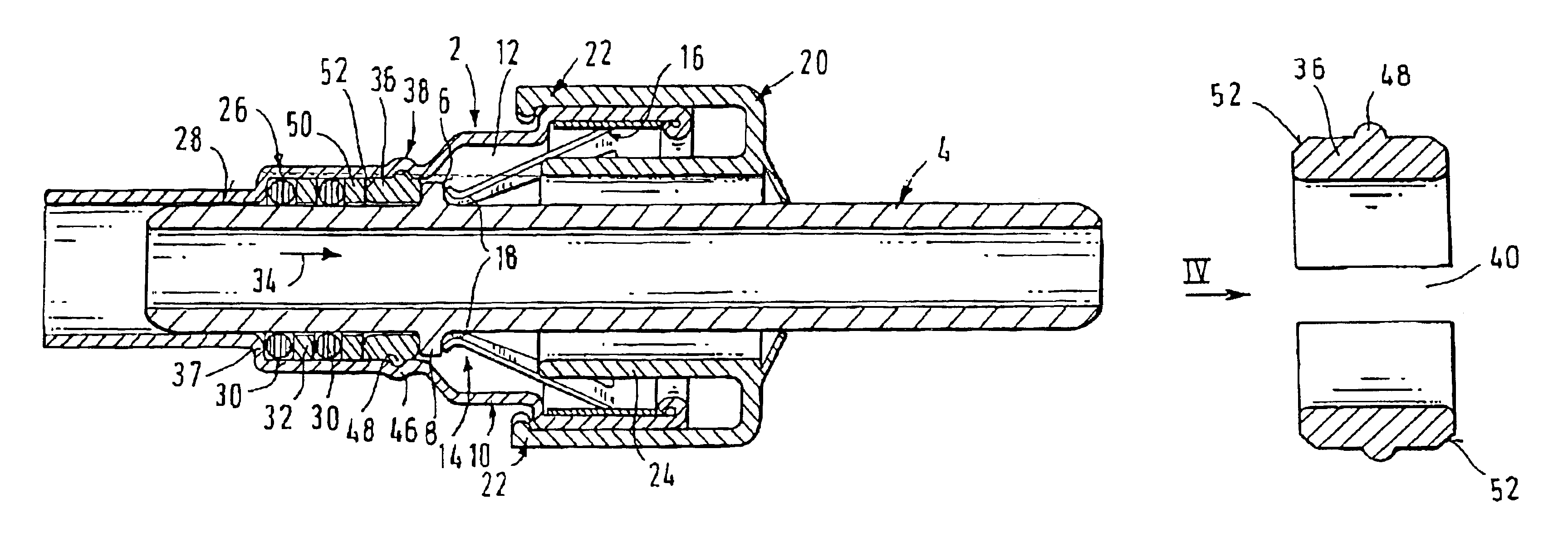
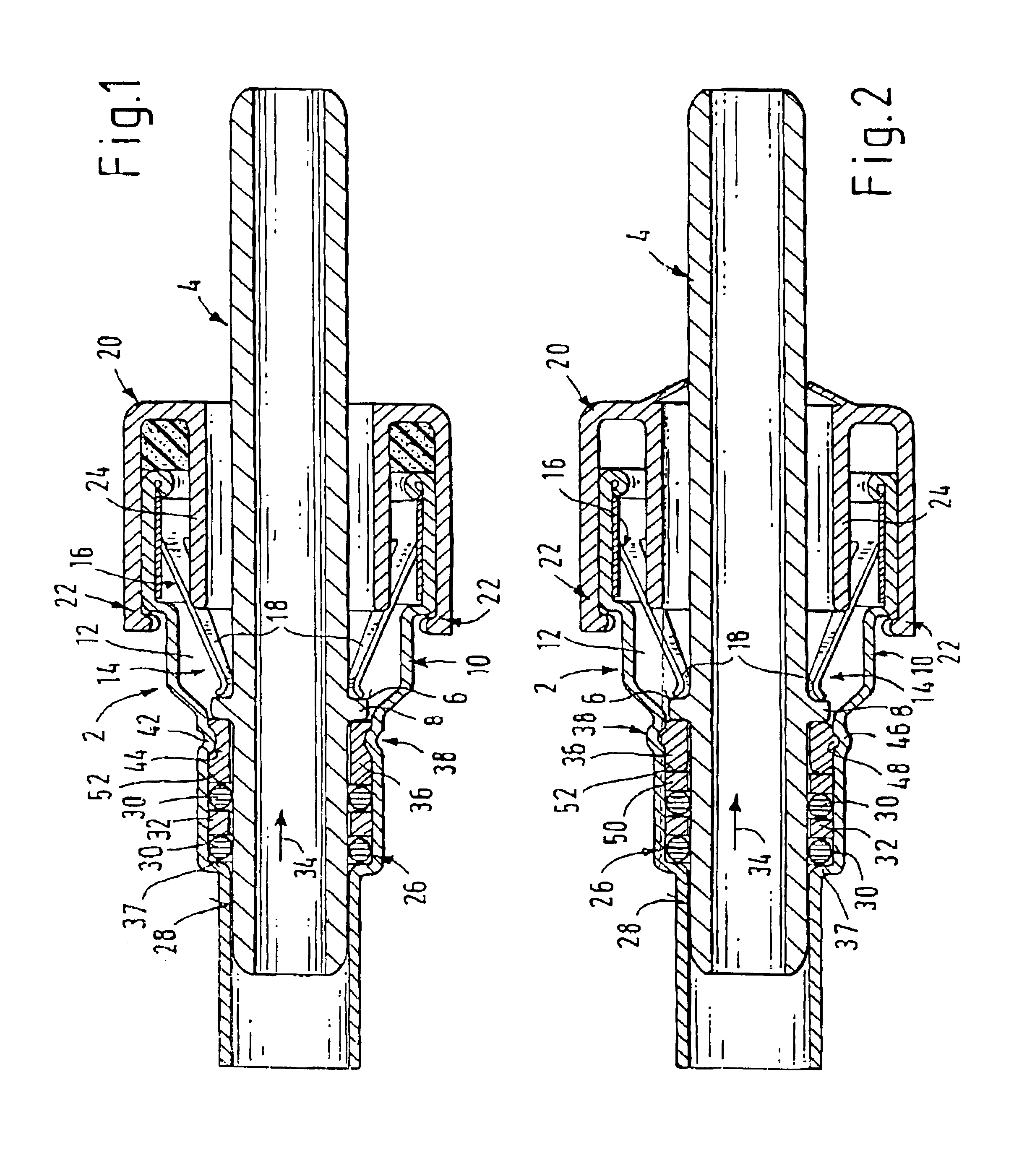
As emerges initially from FIGS. 1 and 2, in each case a plug-in coupling comprises a receiving part 2 and a plug part 4. However, the invention relates only to the receiving part 2 while the plug part 4 has a standard design (“SAE plug”) in the form of a section of pipe which has an annular projection 8 so as to form a radial retaining step 6 on its outer circumference.

The receiving part 2 comprises a socket housing 10 having a plug-in opening 12 for the plug part 4 and having a retaining device 14 for releasably fixing the plugged-in plug part 4 in place. For this purpose, the retaining device 14 has a retaining element 16 which is mounted in the socket housing 10. This retaining element 16 having radially elastically deformable retaining sections 18 for latching engagement behind the retaining step 6 of the plug part 4.

The receiving part 2 furthermore has a release element 2...


PUM


Abstract

A receiving part of a fluid plug-in coupling is provided. The receiving part comprises a socket housing having a plug-in opening for a plug part and a sealing arrangement, which is arranged in the socket housing, for the plugged-in plug part. In this case, the sealing arrangement is fixed axially in the removal direction of the plug part by a closing bushing, and the closing bushing is secured directly in the socket housing via a locking portion.

Description

BACKGROUND OF THE INVENTIONThe present invention relates to a receiving part of a fluid plug-in coupling (the term fluid refers to any hydraulic or gaseous flow media) comprising a socket housing and a sealing arrangement. The socket housing having a plug-in opening for a plug part. The sealing arrangement being arranged in the socket housing and adapted to interface with the plug part. The sealing arrangement being fixed axially in the removal direction of the plug part by means of a closing bushing.EP 0 485 214 B1 describes a receiving part of this type in which the closing bushing is arranged in the socket housing by resting axially on a retaining element. The retaining element, as a stamped and bent sheet-metal part, is mounted in the widened region of the socket housing and, for the locking of a plugged-in plug part, has radially spring elastic latching arms which engage in a latching manner behind a radial retaining step of the plug part. On its end region facing the closing b...

Claims


Application Information

Patent Timeline
Patent Type & Authority Patents(United States)
IPC IPC(8): F16L37/00F16L37/098F16L37/084
CPCF16L37/0987F16L37/0982
Inventor KAMINSKI, VOLKERSERDARIS, JANNISTERLAU, NORBERTZENSES, FRANK
Owner VOSS AUTOMOTIVE
Why Eureka
Try Eureka