Method for producing an aromatic carbonate

a technology of aromatic carbonate and carbonate, which is applied in the field of aromatic carbonate production, can solve the problems of high maintenance cost of production equipment, difficulty in waste disposal and the like, and the use of dichloromethane has been attracting attention, and achieves simple and efficient production and high purity

Active Publication Date: 2007-03-08
ASAHI KASEI KK
View PDF2 Cites 27 Cited by
  • Summary
  • Abstract
  • Description
  • Claims
  • Application Information

AI Technical Summary

Benefits of technology

[0029] In this situation, the present inventors have made extensive and intensive studies with a view toward solving the above-mentioned problems accompanying the prior art. In their studies, the present inventors have utilized the techniques of their previous inventions of WO 03/055840 and WO 04/014840, each of which is directed to a method for continuously producing a dialkyl carbonate, which method comprises reacting an organometal compound, carbon dioxide, and optionally an alcohol with each other to obtain a reaction mixture containing a dialkyl carbonate, separating the dialkyl carbonate from the reaction mixture to obtain a residual liquid, regenerating the organometal compound from the residual liquid, and recycling the regenerated organometal compound. As a result, the present inventors have succeeded in improving the above-mentioned previous inventions and arrived at the present invention. That is, it has been found that all of the problems accompanying the prior art can be solved by a method comprising: (1) performing a reaction between an organometal compound and carbon dioxide to obtain a reaction mixture containing

Problems solved by technology

Recently, the problem of water pollution due to an alkyl halide has arisen and, hence, the melt method which does not use dichloromethane has been attracting attention.
However, since method 1) employs phosgene which is extremely toxic and highly corrosive, method 1) is disadvantageous in that the transportation and storage of phosgene needs great care, and the maintenance of production equipment is costly, which maintenance is indispensable for assuring safety.
Further, in method 1), hydrochloric acid which is highly corrosive is by-produced in a large amount, thereby causing difficulty in the waste disposal and the like.
Moreover, since the aromatic carbonate (e.g., diphenyl carbonate) obtained by method 1) inevitably contains a chlorine-containing compound as an impurity, method 1) also poses the following serious problem.
When such an aromatic carbonate containing a chlorine-containing compound is used for producing a polycarbonate by the melt method, the chlorine-containing compound, even if the amount thereof in the aromatic carbonate is very small, causes the deactivation of a catalyst used for producing a polycarbonate and the discoloration of the polycarbonate produced.
As seen from the above, method 1) has a number of serious problems, such as the use of a toxic substance as a raw material, the by-production of a corrosive compound, and the impurity (such as a chlorine-containing compound) contained in the aromatic carbonate produced.
Carbon monoxide used in method 2) is extremely toxic.
Therefore, the transportation and handling of carbon monoxide require great care, and the maintenance of the production equipment is costly, which maintenance is indispensable for assuring safety in the production of the aromatic carbonate.
Moreover, method 2) employs, as a catalyst, palladium which is expensive and difficult to recover.
Therefore, method 2) inevitably becomes an extremely expensive and complicated method.
Thus, method 2) also has a number of serious problems, such as the use of a toxic compound as a raw material, the corrosion caused by chlorine, the chlorine-containing impurities contained in the aromatic carbonate produced, and a high production cost.
However, this method also poses a problem in that a large amount of a chlorine-containing compound is used in the oxidative carbonylation reaction, so that the chlorine-containing compound is contained in the dimethyl carbonate produced by the oxidative carbonylation reaction or corrodes the production equipment used in this method (see, e.g., patent document 3 below).
Therefore, if the produced diaryl carbonate as such is used without purification for producing a polycarbonate, the polycarbonate produced is inevitably discolored to assume a yellow color

Method used


Image

  • Method for producing an aromatic carbonate
  • Method for producing an aromatic carbonate
  • Method for producing an aromatic carbonate

Examples


example 1

(Production of Dibutyltin Dialkoxide)

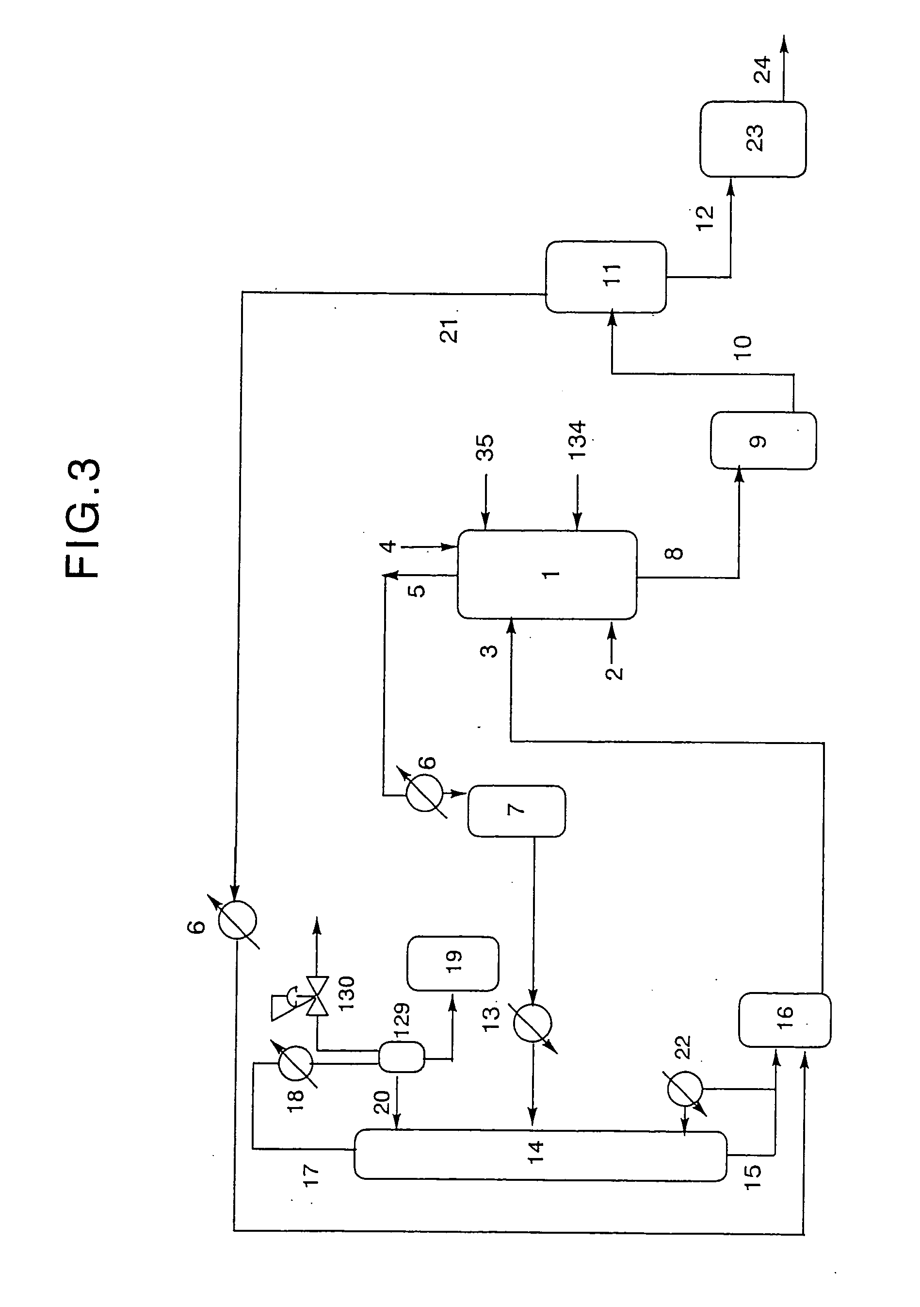
[0451] Using a device as shown in FIG. 3, dibutyltin dialkoxides were produced as follows.

[0452] Into a 5-liter SUS reaction vessel 1 equipped with a stirrer, a heater and a baffle were charged 75 g (0.3 mol) of dibutyltin oxide and 2,224 g (30 mol) of 1-butanol (manufactured and sold by Aldrich, U.S.A.), wherein dibutyltin oxide was fed through conduit 4 provided at the top of reaction vessel 1, and 1-butanol was fed from alcohol reservoir 16 through conduit 3 provided at an upper portion of reaction vessel 1. Further, nitrogen gas was fed to reaction vessel 1 through a SUS tube connected to inert gas conduit 2 provided at a lower portion of reaction vessel 1 at a rate of 0.1 Nl / hr.

[0453] Subsequently, the contents of reaction vessel 1 were heated while stirring, so as to adjust the temperature thereof within the range of from 113° C. to the boiling point of 1-butanol, thereby performing a reaction for about 6 hours while discharging the low...

example 2

(Production of Dibutyltin Dialkoxide)

[0485] Using a device as shown in FIG. 3, dibutyltin dialkoxides were produced as follows.

[0486] Into a 5-liter SUS reaction vessel 1 equipped with a stirrer, a heater and a baffle were charged 75 g (0.3 mol) of dibutyltin oxide and 2,224 g (30 mol) of 1-butanol (manufactured and sold by Aldrich, U.S.A.), wherein dibutyltin oxide was fed through conduit 4 provided at the top of reaction vessel 1, and 1-butanol was fed from alcohol reservoir 16 through conduit 3 provided at an upper portion of reaction vessel 1. Further, nitrogen gas was fed to reaction vessel 1 through a SUS tube connected to inert gas conduit 2 provided at a lower portion of reaction vessel 1 at a rate of 0.1 Nl / hr.

[0487] Subsequently, the contents of reaction vessel 1 were heated while stirring, so as to adjust the temperature thereof within the range of from 113° C. to the boiling point of 1-butanol, thereby performing a reaction for about 6 hours while discharging low boi...

example 3

(Production of Dibutyltin Dialkoxide)

[0516] Using a device as shown in FIG. 3, dibutyltin dialkoxides were produced as follows.

[0517] Into a 5-liter SUS reaction vessel 1 equipped with a stirrer, a heater and a baffle were charged 75 g (0.3 mol) of dibutyltin oxide and 2,075 g (28 mol) of 1-butanol (manufactured and sold by Aldrich, U.S.A.), wherein dibutyltin oxide was fed through conduit 4 provided at the top of reaction vessel 1, and 1-butanol was fed from alcohol reservoir 16 through conduit 3 provided at an upper portion of reaction vessel 1. Further, nitrogen gas was fed to reaction vessel 1 through a SUS tube connected to inert gas conduit 2 provided at a lower portion of reaction vessel 1 at a rate of 0.1 Nl / hr.

[0518] Subsequently, the contents of reaction vessel 1 were heated while stirring, so as to adjust the temperature thereof within the range of from 113° C. to the boiling point of 1-butanol, thereby performing a reaction for about 6 hours while discharging low boi...


PUM

PropertyMeasurementUnit
Temperatureaaaaaaaaaa
Fractionaaaaaaaaaa

Abstract

A method for producing an aromatic carbonate, comprising: (1) performing a reaction between an organometal compound and carbon dioxide to obtain a reaction mixture containing a dialkyl carbonate formed by the reaction, (2) separating the dialkyl carbonate from the reaction mixture to obtain a residual liquid, (3) reacting the residual liquid with an alcohol to form at least one organometal compound and form water and removing the water from the organometal compound, and (4) reacting the dialkyl carbonate separated in step (2) with an aromatic hydroxy compound to obtain an aromatic carbonate.

Description

BACKGROUND OF THE INVENTION [0001] 1. Field of the Invention [0002] The present invention relates to a method for producing an aromatic carbonate. More particularly, the present invention is concerned with a method for producing an aromatic carbonate, comprising: (1) performing a reaction between an organometal compound and carbon dioxide to obtain a reaction mixture containing a dialkyl carbonate formed by the reaction, (2) separating the dialkyl carbonate from the reaction mixture to obtain a residual liquid, and performing the following steps (3) and (4) in either order, or partially or wholly simultaneously: (3) reacting the residual liquid with an alcohol to form at least one organometal compound and form water and removing the water from the organometal compound, and (4) reacting the dialkyl carbonate separated in step (2) with an aromatic hydroxy compound to obtain an aromatic carbonate. [0003] The method of the present invention is advantageous not only in that the method do...

Claims


Application Information

Patent Timeline
IPC IPC(8): C08G64/00C07C68/04C07C68/06
CPCC07C68/04C07C68/06C07C69/96
Inventor MIYAKE, NOBUHISAWATANABE, TOMOARIONISHI, KAZUHIROSATO, AKIHIRO
Owner ASAHI KASEI KK
Why Eureka
Try Eureka