Main handle with a safety lock

a safety lock and handle technology, applied in the field of main handle of power tools, can solve the problems of easy damage of anti-switch-on devices, easy malfunction, complicated assembly, etc., and achieve the effect of simple construction and less susceptible to damag

Inactive Publication Date: 2008-01-17
HILTI AG
View PDF4 Cites 20 Cited by
  • Summary
  • Abstract
  • Description
  • Claims
  • Application Information

AI Technical Summary

Benefits of technology

[0007]It is the object of the present invention to overcome the above-mentioned disadvantages in a main handle with a grip of a motor switch and a safety lock and to ensure a simple construction which is less susceptible to damage.

Problems solved by technology

The known grip is disadvantageous in that the anti-switch-on device has a relatively large number of individual parts and is therefore relatively complicated to assemble and relatively susceptible to malfunction.
Further, the press button which projects relatively far out of the tool housing often jams, for example, when the power tool is put away into a tool box, so that the anti-switch-on device can easily be damaged.

Method used


Image

  • Main handle with a safety lock
  • Main handle with a safety lock
  • Main handle with a safety lock

Examples


Embodiment Construction

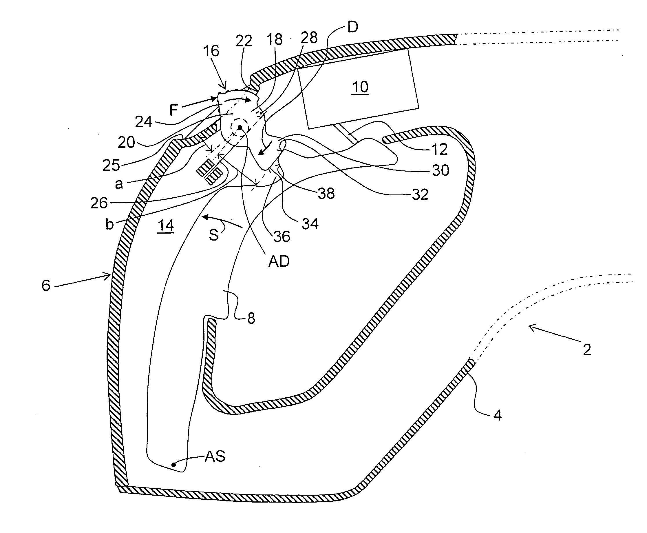
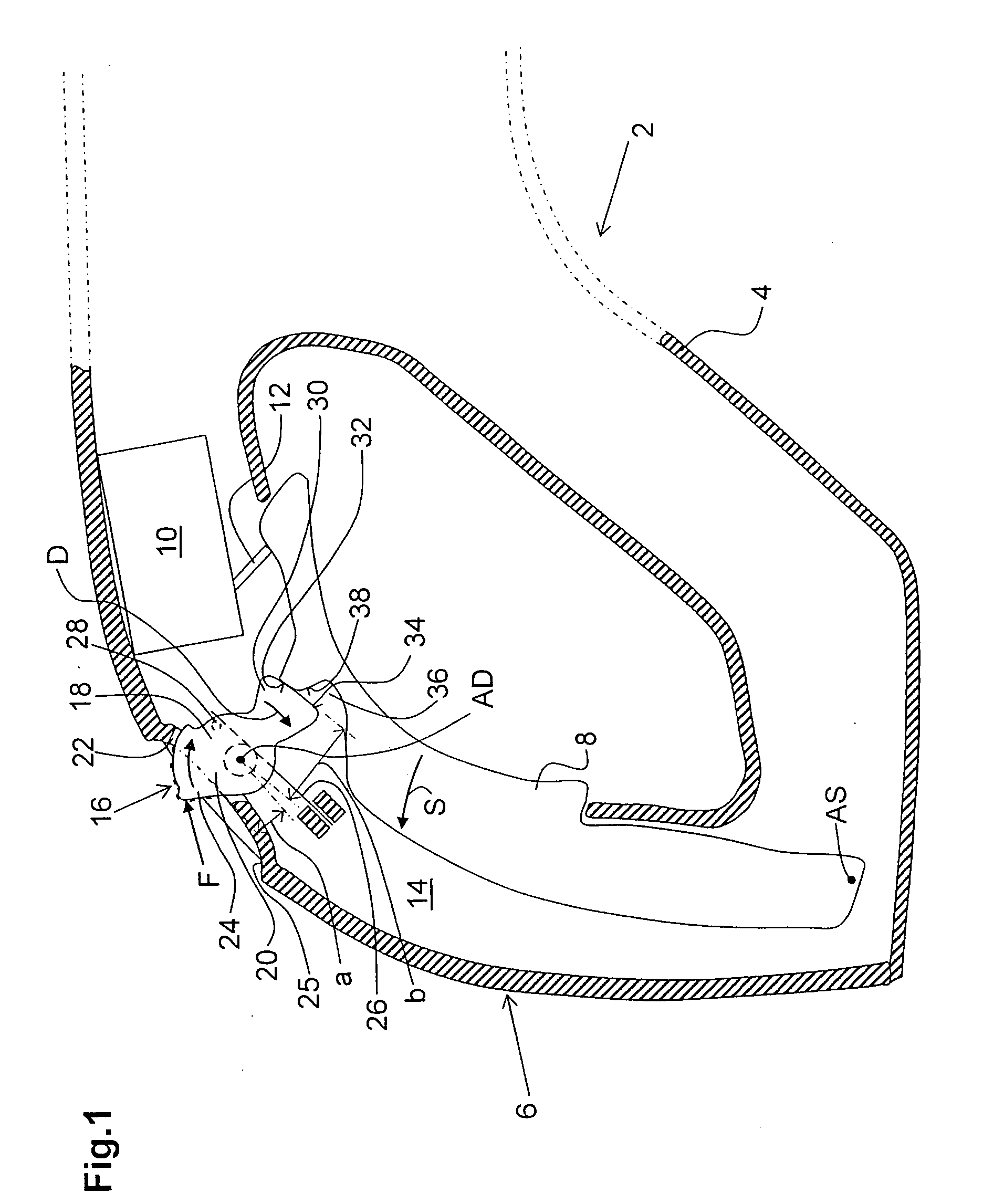
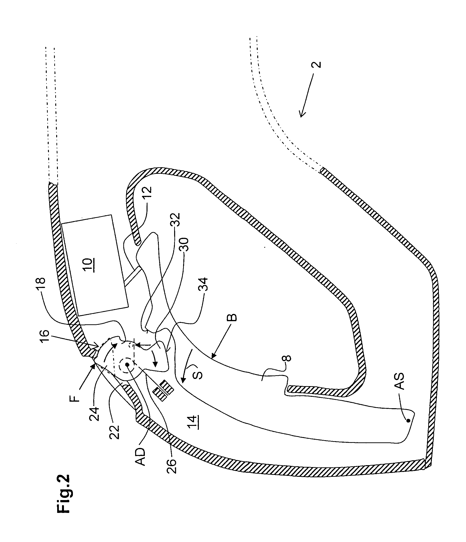
[0018]FIG. 1 shows an end of an electrically operated hand-held power tool 2 in the form of a severing tool or grinding tool, which end is remote of a tool holder, not shown. This hand-held power tool 2 has a tool housing 4 which forms an arc-shaped main handle 6 at this end. A grip 8 for actuating a motor switch 10 by a hand holding the main handle 6 by means of a switching member 12 is provided on this main handle 6. The motor switch 10 is arranged in a housing interior 14 which is defined by the tool housing 4. The grip 8 is formed by a switch pawl that is held so as to be swivelable along a swiveling direction S around a swiveling axis AS. Actuation of the motor switch 10 is possible in various positions of the hand holding the main handle 6 by means of this grip 8. In FIG. 1, the grip 8 is in a passive position in which the motor switch 10 is not actuated.

[0019]Further, a safety lock, designated in its entirety by 16, is provided at the main handle 6. This safety lock 16 substa...


PUM


Abstract

A main handle for an electrically operated power tool and in which a grip (8) of a motor switch (10) and an actuating element serving to unlock a safety lock (16) are arranged on the main handle (6) of the electrically operated power tool (2), with the actuating element having an actuating portion (24) which is accessible from outside a tool housing (4), with the safety lock (16) blocking actuation of the motor switch (10) in its normal position with a blocking area (34) which is swivelable in a movement path of the grip (8), and being movable, upon actuation of the actuating element, into a release position in which the actuation of the motor switch (10) is unblocked, and with the actuating element being formed by a rotatably supported turning element (18) at which the blocking area (34) is formed.

Description

BACKGROUND OF THE INVENTION[0001]1. Field of the Invention[0002]The invention is directed to a main handle of a power tool that is operated by an electric motor. A grip of a motor switch and actuating means serving to unlock a safety lock are provided on this main handle. The actuating means have an actuating portion which is accessible from outside tool housing. The safety lock blocks actuation of the motor switch in a normal position by means of a blocking area which is swivelable in a movement path of the grip. By actuating the actuating means, the safety lock can be moved into a release position in which the actuation of the motor switch is unblocked.[0003]2. Description of the Prior Art[0004]In main handles of the type mentioned above, it is possible to actuate the motor switch with a hand holding the main handle by actuating the grip which accordingly sets the power tool in operation. In addition, the safety lock is provided in order to prevent the power tool from being switch...

Claims


Application Information

Patent Timeline
Patent Type & Authority Applications(United States)
IPC IPC(8): H01H9/28
CPCH01H9/06B25F5/02H01H3/20
Inventor LIEBERT, BERNHARDBLATZ, THOMAS
Owner HILTI AG
Why Eureka
Try Eureka