
Method And Device For Constructing High-Power LED Lighting Fixture

a technology of led lighting fixtures and lighting supports, applied in the direction of lighting and heating equipment, fixed installation, lighting support devices, etc., can solve the problems of high production costs, inconvenient use, difficult maintenance, etc., to facilitate standardization of production, reduce production costs and design costs, and high commonality

Inactive Publication Date: 2014-02-13
GUIZHOU GUANGPUSEN PHOTOELECTRIC
View PDF23 Cites 27 Cited by
  • Summary
  • Abstract
  • Description
  • Claims
  • Application Information

AI Technical Summary

Benefits of technology

The present invention provides a method and device for constructing a high-power LED lighting fixture. This method shortens the production process of the LED lighting fixture and improves mass productivity. The fixture is designed with a standard-interface LED lamp head that can be used for different LED lighting fixtures as a universal component, simplifying the design and production process. The heat dissipation design allows for effective heat conduction and simplifies the heat dissipation process. The standard-interface LED lamp head is easy to install and maintain, and the fixture is convenient to remove and replace. The distribution circle of screw holes on the connection component has predetermined dimensions depending on the power of LED, making it easy to standardize the production and maintenance. The present invention standardizes the lighting source of the high-power LED lighting fixture, reducing production and design costs, and promoting its popularization.

Problems solved by technology

This causes a series of vital problems such as high production costs, inconvenient use, difficult maintenance, and so on, to the LED lighting fixture.
First, it is impossible to achieve uniform standardized production throughout the country or even the world, which results in too many sizes of products and expensive costs.
Second, an LED lighting fixture user may relate to products of several or even tens of producers, since the products are not be interchangeable with each other.
Third, the LED optical module, the power source and the lamp casing should be removed wholly during repairing, which may easily cause other failures, extended maintenance time and high maintenance costs.
The wide use of the high-power LED is extremely limited by these disadvantages.

Method used


Image

  • Method And Device For Constructing High-Power LED Lighting Fixture
  • Method And Device For Constructing High-Power LED Lighting Fixture
  • Method And Device For Constructing High-Power LED Lighting Fixture

Examples


example 1

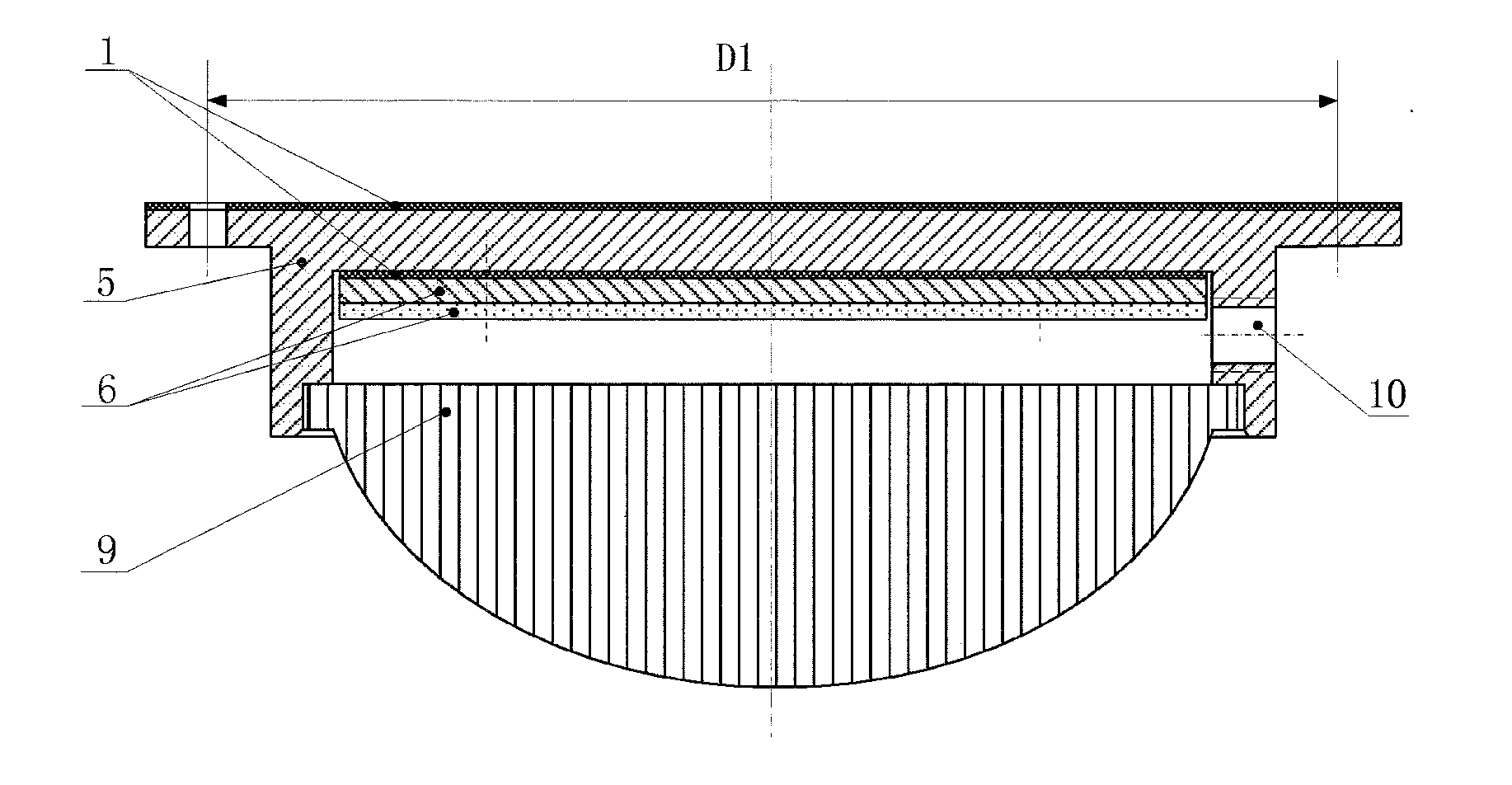
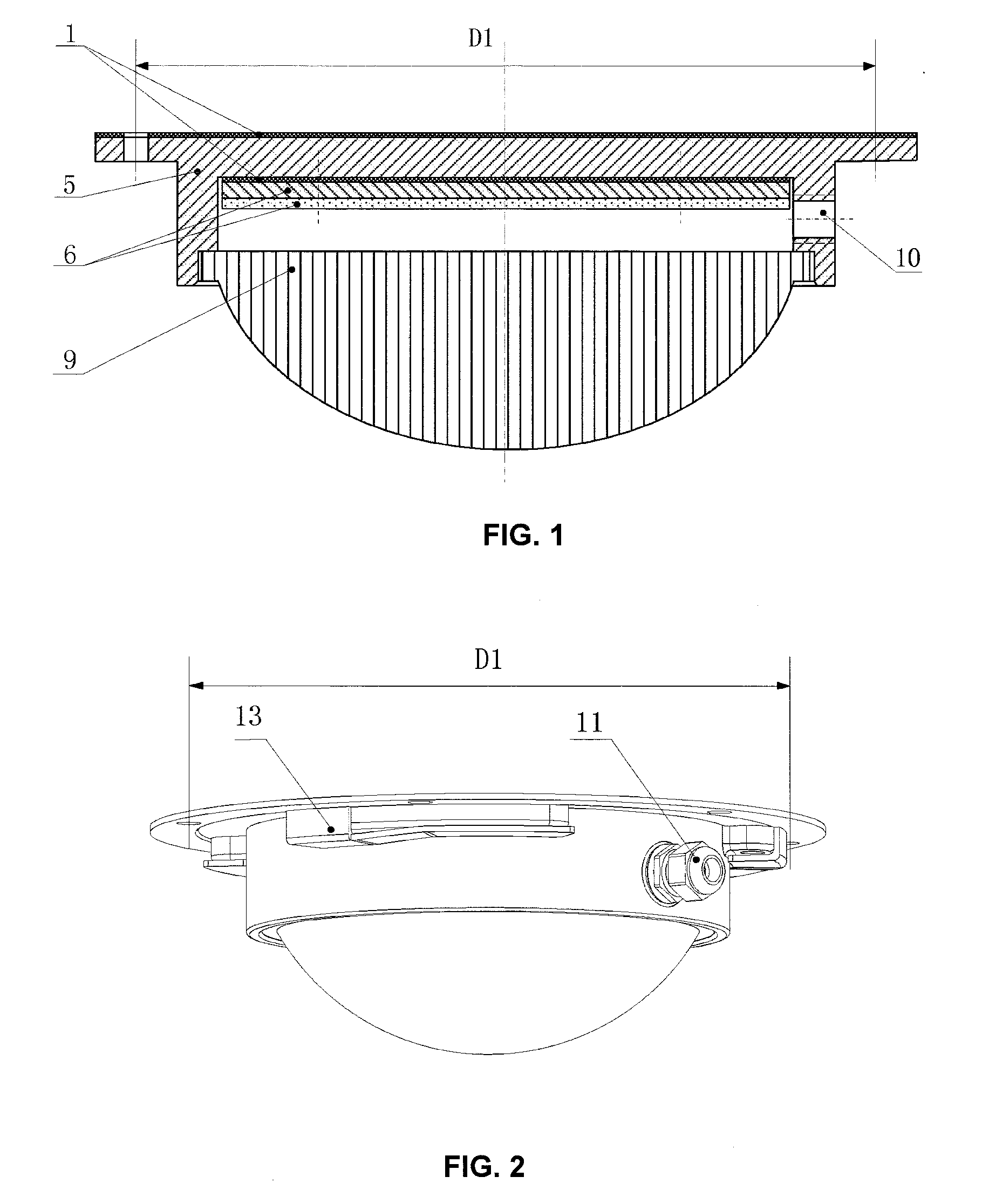
[0051]With reference to FIG. 1, a standard-interface LED lamp head can comprise a lamp frame 5. A lamp bead integration module 6 in which an LED optical module and a separate power source are integrated can be provided in the lamp frame 5. A superconductive graphite pad 1 can provided between the lamp frame 5 and the lamp bead integration module 6, and a through hole 10 is provided in the lamp frame 5. The lamp frame 5 can be provided with a flange and thereby can be fixed to the lamp base through screws. A diameter D1 of a distribution circle of screw holes on the flange or a diameter D1 of a distribution circle of screw holes on the seat 2 may be selected from several predetermined dimensions depending on the power of LED so as to facilitate the standardization of production and maintenance. Alternatively, the lamp frame 5 can be provided with a screw thread, a bayonet, or a snap spring and thereby can be connected with the seat 2 fixed on the lamp base so as to generate a heat co...

example 2

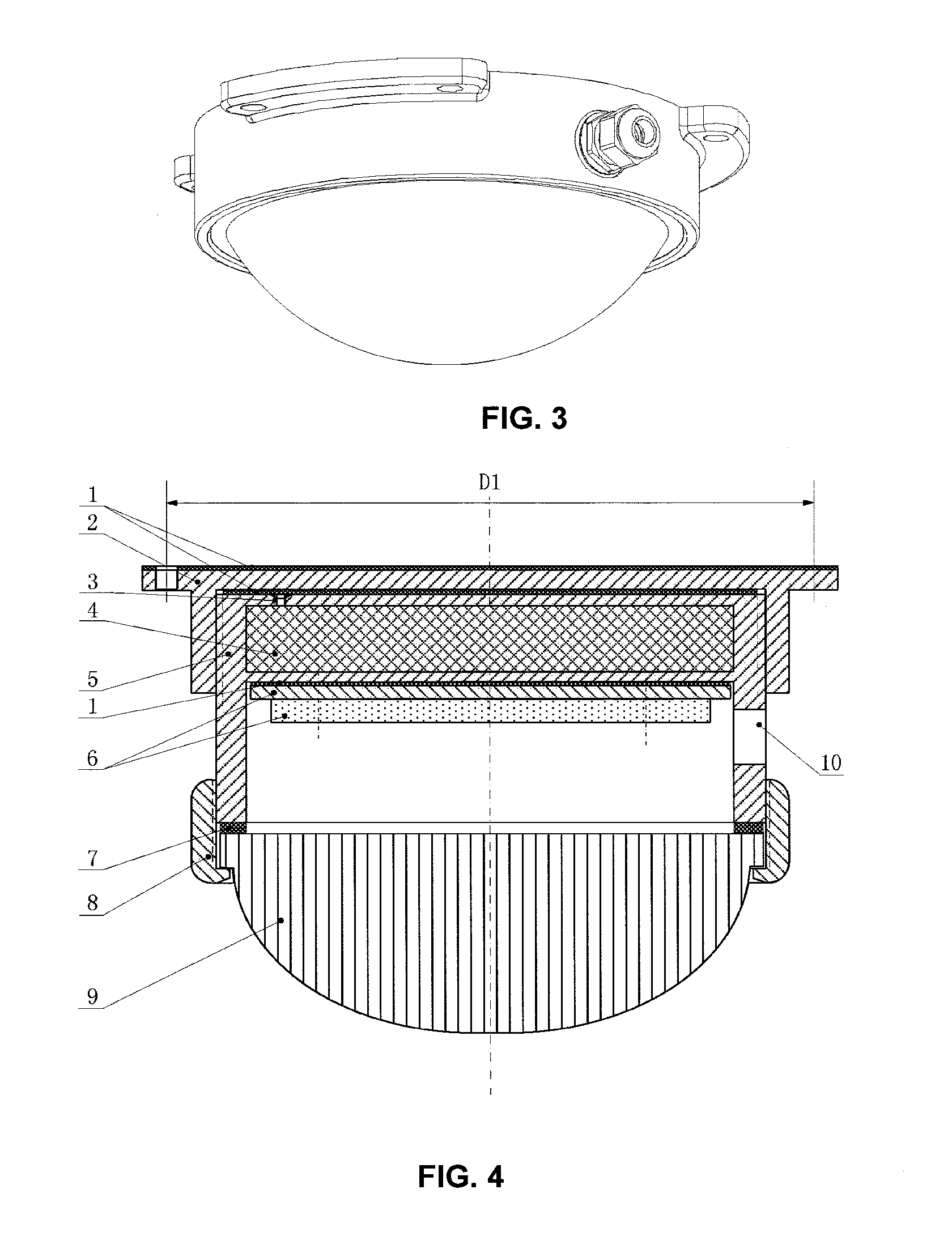
[0052]With reference to FIG. 2, a standard-interface LED lamp head (standard high-power outdoor LED lamp head with screw thread connection) can comprise a lamp frame 5. A lamp bead integration module 6 (in which an LED optical module and an independent driving power source are integrated) can be provided in the lamp base 5. A superconductive graphite pad 1 can be provided between the lamp frame 5 and the lamp bead integration module 6, and a through hole 10 for threading wires can be provided in the lamp frame 5. A waterproof coupler 11 is provided at the through hole 10. The lamp frame 5 is fixed onto the lamp base 2 though a lamp head screw thread of the national standard E27, and a superconductive graphite pad 1 can be provided between the lamp frame 5 and the lamp base 2. A superconducting liquid 4 can also be provided in the lamp frame 5. A lens 9 (convex lens) can be provided on the lamp frame 5. The lens 9 (convex lens) can be connected with the lamp frame 5 through a lens co...

example 3

[0053]With reference to FIG. 5, a standard-interface LED lamp head (standard high-power outdoor LED lamp head with screw thread connection) can comprise a lamp frame 5. A lamp bead integration module 6 in which an LED optical module and an independent driving power source are integrated can be provided in the lamp frame 5. A superconductive graphite pad 1 can be provided between the lamp frame 5 and the lamp bead integration module 6, and a through hole 10 for threading wires can be provided in the lamp frame 5. A waterproof coupler can be provided at the through hole 10. The lamp frame 5 can be provided with a international standard screw thread and thereby can be fixed onto the lamp base 2. A superconductive graphite pad 1 is arranged between the lamp frame 5 and the lamp base 2. A superconducting liquid 4 can also be provided in the lamp frame 5. A lens 9 (planar lens) can be provided on the lamp frame 5. The lens 9 (planar lens) can be connected with lamp frame 5 through a lens ...


PUM

PropertyMeasurementUnit
diameter D1aaaaaaaaaa

Abstract

A method and a device for constructing a high-power LED lighting fixture are disclosed, wherein a high power LED lighting fixture is constructed by assembling one or more standard-interface LED lamp heads, in which an LED optical module and a separate power source are integrated, onto a lamp base (15). This method can have the production process of the LED lighting fixture shortened, and improve its mass productivity.

Description

TECHNICAL FIELD[0001]The present invention relates to a method and a device for constructing a high-power LED lighting fixture, and belongs to the technical field of LED lighting.BACKGROUND[0002]The light emitting diode (LED) has such advantages as the high luminous efficiency, and easy control of the illuminating direction and the luminance. Since the luminous efficiency of most present LED lighting lamps exceeds 70 LM / W, it has an energy-saving advantage over the conventional energy-saving lamp. Theoretically, the luminous efficiency of a green light emitting diode may be up to 683 LM / W, and the theoretical luminous efficiency of a white light emitting diode may be up to 182.45 LM / W, thus the luminous efficiency of LED could be increased greatly.[0003]In the design of the current high-power LED lighting fixture, especially in that of the high-power LED lamp such as a street lamp etc., when assembling a high-power LED lighting fixture, an LED optical module, a power source and a la...

Claims


Application Information

Patent Timeline
Patent Type & Authority Applications(United States)
IPC IPC(8): F21K99/00F21S2/00
CPCF21K9/00F21K9/30F21S2/005F21K9/90F21S8/086F21V19/001F21V21/30F21W2131/103F21V29/58F21K9/20F21K9/69F21Y2115/10Y10T29/49117
Inventor ZHANG, JIQIANGZHANG, ZHEYUAN
Owner GUIZHOU GUANGPUSEN PHOTOELECTRIC
Learn More