
Fiber optic installation

a fiber optic and installation technology, applied in the field of fiber optic installation, can solve the problems of disadvantageous laying machine and material outlay, and achieve the effects of reducing the overall line-laying cost, reducing the cost of laying method, and increasing operational reliability

Inactive Publication Date: 2005-03-15
CCS TECH INC
View PDF48 Cites 53 Cited by
  • Summary
  • Abstract
  • Description
  • Claims
  • Application Information

AI Technical Summary

Benefits of technology

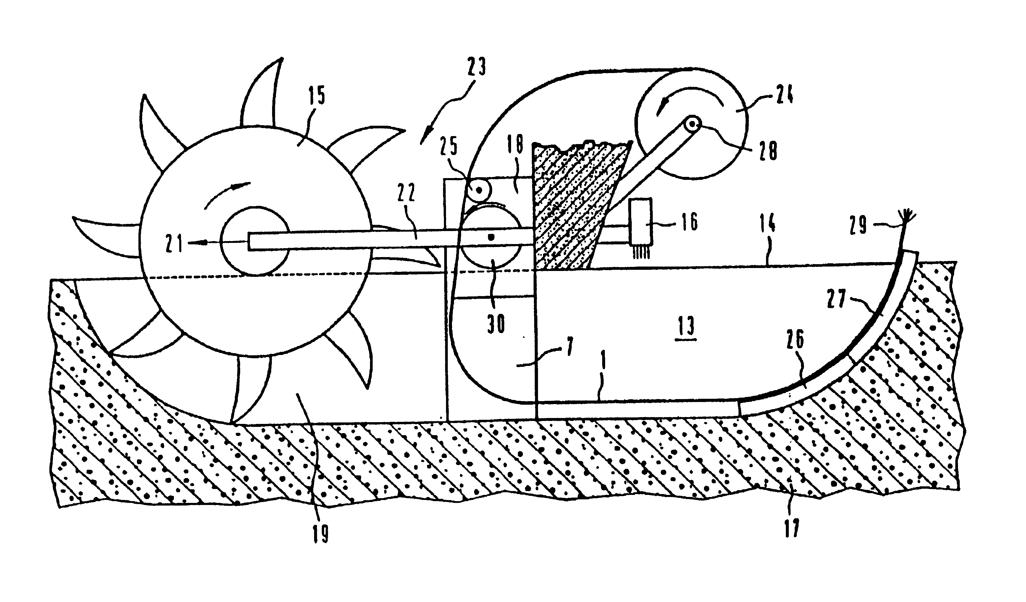
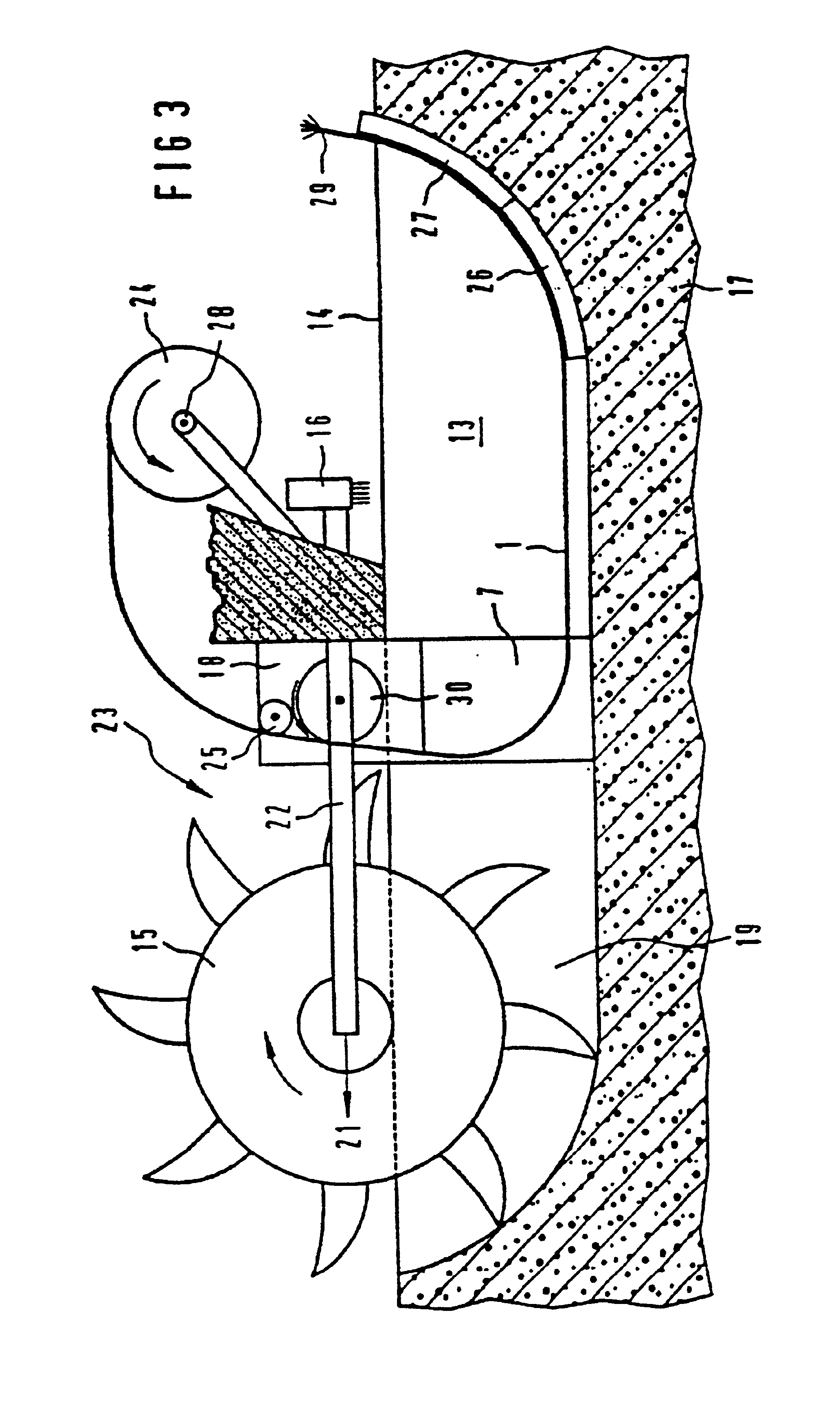
A great advantage of the process according to the invention is that only a relatively short amount of time is taken for the laying operation, with the result that it is used particularly wherever long-term hold-ups are undesirable. This is the case, for example particularly when laying new or additional cables, when the laying operation has to be carried out in urban areas with heavy traffic. Blocking off or diverting is to be avoided as far as possible. The operations of cutting, laying and sealing the channel can take place directly one after the other, these operations expediently being carried out all in one go by a multipurpose machine. In this manner, the traffic disruption is barely greater than that caused by a road sweeper. There is also such a need, for example, when all the laid pipes, cable ducts or pipelines have already had cables laid in them, it then being possible to splice onto the newly laid cables without interruption. Tubular mini communication cables, which are referred to as microcables or minicables, are particularly suitable for this purpose. These newly laid minicables or microcables may preferably be connected to form a redundant overlay network.
The flexibility of the minicable or of the tube can be improved by a grooved sheath.

Problems solved by technology

The high outlay for laying machines and material is also disadvantageous here.

Method used


Image

  • Fiber optic installation
  • Fiber optic installation
  • Fiber optic installation

Examples


Embodiment Construction

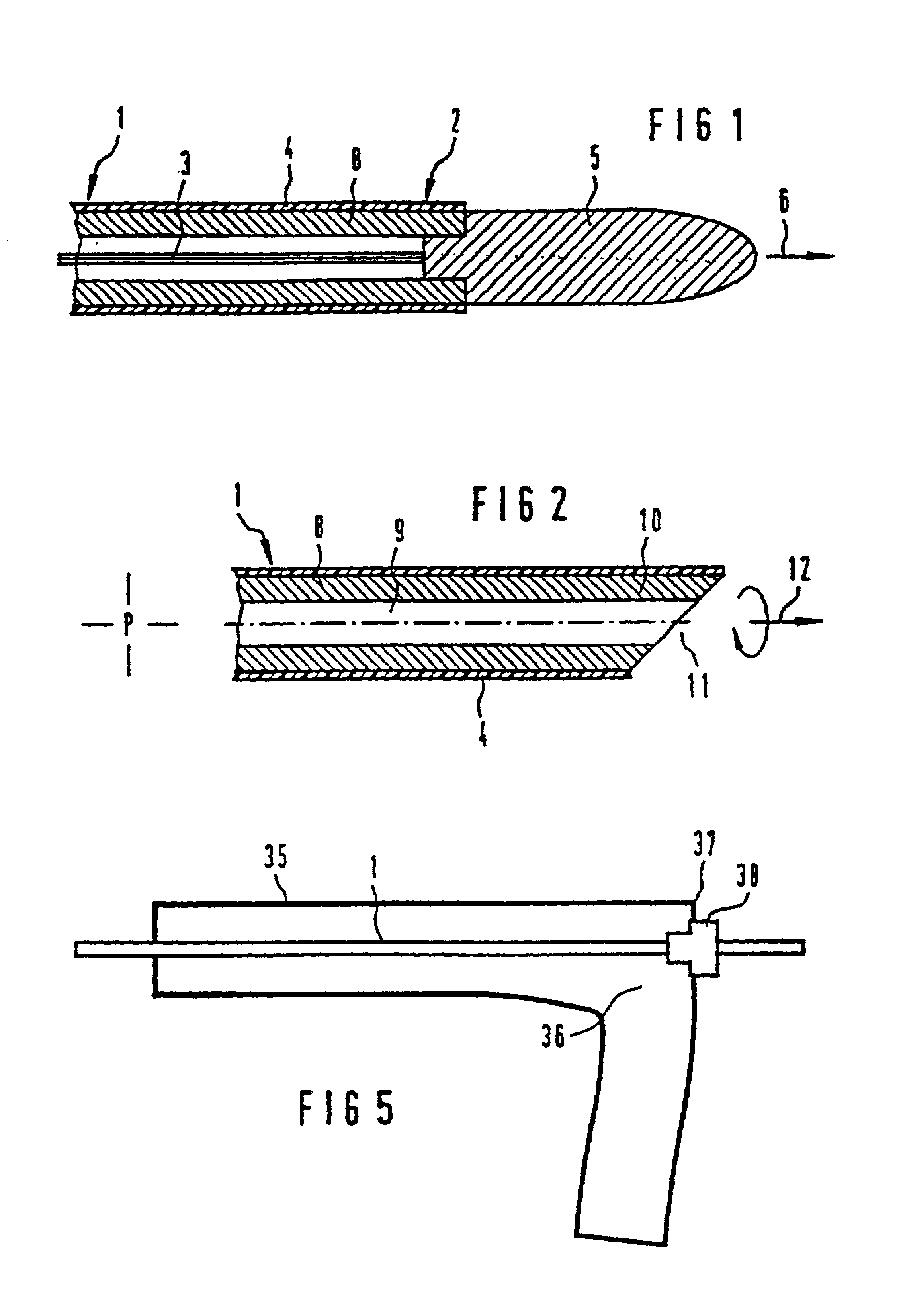
FIG. 1 shows the construction of a tubular microcable or minicable 1, the cable end 2 being provided with a drawing-in or drilling tip 5. The arrow 6 indicates the drilling movement or advancement direction of the drilling head. Running in the interior of the minicable 1 are the optical waveguides 3, which may be introduced either at the factory or after the laying operation. The outer surface of the minicable is provided with a surface protection 4.

FIG. 2, then, shows the tube 8 of the minicable 1, in the interior of which, that is to say in the central duct of which, optical waveguides have not as yet been provided. In this case, the said central duct serves initially as a pressurized jetting duct for the laying operation. Thus, an appropriate medium, for example a suitable liquid, is injected under pressure, with the result that the earth is jetted out and displaced at the end 11 of the minicable. In addition, rotating movement of the drilling tip 10 in accordance with the arrow ...


PUM


Abstract

The invention relates to a process for introducing an optical cable, in the form of a microcable or minicable (1), in solid ground (17) with the aid of a laying unit (23). The microcable or minicable (1) used for this purpose comprises a homogeneous and pressurized-water-tight tube (8) which has an external diameter of from 2.0 to 10 mm and into which optical waveguides (3) are introduced.

Description

FIELD OF THE INVENTIONThe invention relates to a process for introducing an optical cable, consisting of a tube and optical waveguides introduced therein, into solid ground with the aid of a laying unit.BACKGROUND OF THE INVENTIONDE-A1-41 15 907 discloses a cable-laying plough for laying cables in the ground, in particular in the ground under water. In this case, the blade of the cable-laying plough has arranged in front of it a rotating cutting wheel which, in addition, is made to vibrate vertically, with the result that hard objects located in the region of the trench which is to be excavated may thus also be broken up thereby. This cable-laying plough excavates relatively wide trenches by displacing the soil with the aid of the plough blade. Such machines are used, in particular, in coastal areas and under water using corresponding control devices. For laying operations in the ground, the material is usually removed over a width of from 60 to 100 cm and a cable-laying depth of ap...

Claims


Application Information

Patent Timeline
Patent Type & Authority Patents(United States)
IPC IPC(8): G02B6/50G02B6/46G02B6/44H02G1/06H02G1/08H02G1/10H02G9/02H02G9/10
CPCG02B6/4459G02B6/4463G02B6/504E02F5/101H02G1/086H02G9/02H02G9/10H02G1/06G02B6/50
Inventor FINZEL, LOTHARKUNZE, DIETERZEIDLER, GUNTERKOSSAT, RAINER
Owner CCS TECH INC
Learn More