Device for detecting a thermal linear dilation on part of a machine

Inactive Publication Date: 2005-03-15
DR JOHANNES HEIDENHAIN GMBH
View PDF14 Cites 7 Cited by
  • Summary
  • Abstract
  • Description
  • Claims
  • Application Information

AI Technical Summary

Benefits of technology

It is an object of the present invention to disclose a device for detecting the thermally caused linear expansion of a machine element, which can be produced in a cost-effective manner and can be flexibly employed.

Problems solved by technology

Heat is generated in the course of operating a machine tool, for example by the friction of a rotating spindle, which can lead to a thermal expansion of the heated machine element and therefore to inaccuracies of the dimensions of the processed workpiece.

Method used


Image

  • Device for detecting a thermal linear dilation on part of a machine
  • Device for detecting a thermal linear dilation on part of a machine
  • Device for detecting a thermal linear dilation on part of a machine

Examples


Embodiment Construction

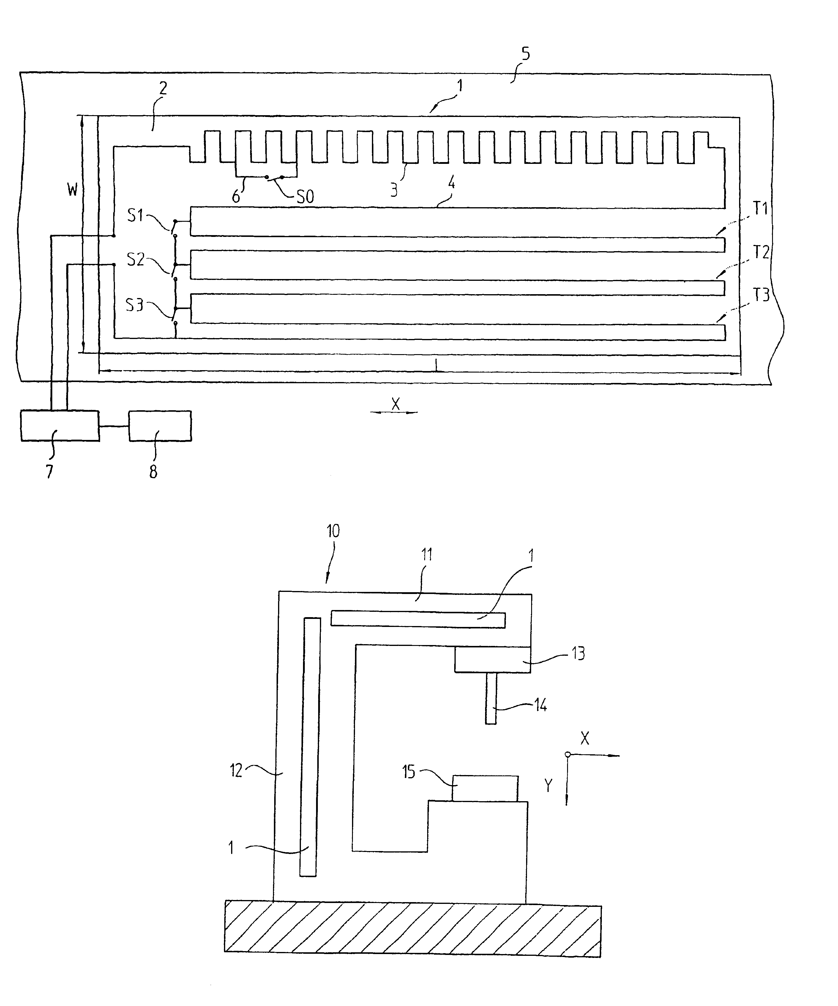
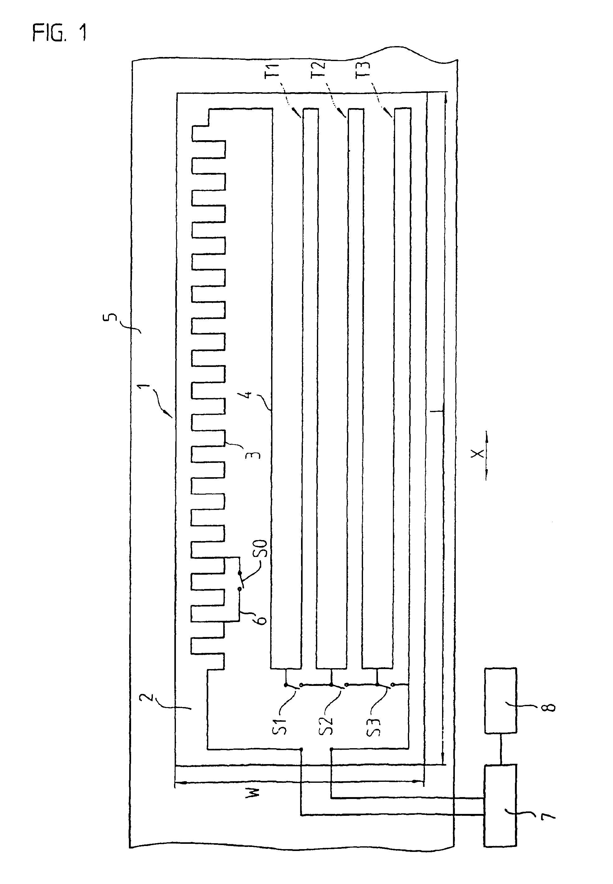
A first simple embodiment of a device for detecting a thermally caused linear expansion is represented in FIG. 1. A temperature sensor 1 includes a printed circuit board substrate 2, which supports a first metallic conductor 3 in the form of a meander-shaped copper track with a return track 4. Let the first metallic conductor 3 have an electrical resistance RO. The trimmer tracks T1 to TN having a resistance of R1 to RN, which are also made of copper tracks and are switched in series with respect to the first metallic conductor 3, can be individually short-circuited by a solder spot via switches S1 to SN, embodied as interrupted copper tracks. In the process, the total resistance of the temperature sensor 1 is respectively reduced by the resistance R1 to RN of the short-circuited trimmer tracks T1 to TN.

In an advantageous manner the resistance value R1 to RN of the individual trimmer tracks T1 to TN doubles, so that R(N+1)=2 * RN applies. Thus, a resistance value between R0 (all tri...


PUM

PropertyMeasurementUnit
Temperatureaaaaaaaaaa
Lengthaaaaaaaaaa
Electrical resistanceaaaaaaaaaa

Abstract

A device for detecting thermally caused linear expansions of a machine element, wherein the device includes a temperature sensor placed along an expansion direction. The temperature sensor includes a first metallic conductor having an electrical resistance that is proportional to an average temperature of an area to be monitored and a plurality of trimmer tracks in the form of further metallic conductors placed next to the first metallic conductor. The temperature sensor further includes electrical connections selectively interconnecting the plurality of trimmer tracks with the first metallic conductor and wherein the plurality of the trimmer tracks have an effective electrical resistance that is proportional to the average temperature of the area to be monitored.

Description

BACKGROUND OF THE INVENTION1. Field of the InventionThe present invention relates to a device for detecting a thermally caused linear expansion of a machine element of, for example, a machine tool.2. Description of the Related ArtHeat is generated in the course of operating a machine tool, for example by the friction of a rotating spindle, which can lead to a thermal expansion of the heated machine element and therefore to inaccuracies of the dimensions of the processed workpiece. If the expansions are known, it is possible to achieve an improved dimensional accuracy of the workpiece by an appropriate readjustment.DE 38 22 873 C1 describes a device for measuring and adjusting thermally caused linear expansions of machines, in particular machine tools. In the process the electrical resistance of a temperature sensor made of platinum, which is in thermal contact with an area of the machine element, is used as the measurement of the thermal linear expansion of the machine element in th...

Claims


Application Information

Patent Timeline
IPC IPC(8): G01B7/16G05B19/404G01K7/25B23Q17/00
CPCG01B7/20G05B19/404G05B2219/37274Y10S33/19Y10T409/306832Y10T409/308008Y10T409/307224Y10T409/309744Y10T409/304648Y10T409/303976Y10T408/16
Inventor BRAASCH, JANMULLER, JOSEFSEICHTER, MARTIN
Owner DR JOHANNES HEIDENHAIN GMBH
Why Eureka
Try Eureka