Method of using a robotic containerization and palletizing system

a containerization and palletizing system technology, applied in the field of robotic containerization and palletizing system, can solve the problem of reducing the floor space needed for the system, and achieve the effect of shortening the clamp travel, improving speed performance and system throughput, and less room for the gripper to actua

Inactive Publication Date: 2005-03-15
ABB FLEXIBLE AUTOMATION INC
View PDF39 Cites 16 Cited by
  • Summary
  • Abstract
  • Description
  • Claims
  • Application Information

AI Technical Summary

Benefits of technology

The offset-finger gripper is designed to grasp the mail trays / tubs from the sides and bottom. The fingers rotate 90 degrees to release the grasped tray / tub when the clamp cylinder is relaxed. The gripper uses a multiple pressure clamp cylinder which allows the selection of high or low clamp force to accommodate and adjust to heavy tubs and lightweight trays. The gripper also includes a valve and proximity switch, which permit the clamp cylinder to be adjusted at both an intermediate open position and a full open position. This feature allows the robot to pick up a tray / tub from a direction perpendicular to the product's long axis. It also shortens clamp travel to close, improving speed performance and system throughput.
The present invention utilizes a top-loading technique. Mail containers are approached from the top and loaded into carts and onto pallets in a similar fashion. Top loading requires less room for the gripper to actuate and, thus, reduces the floor space needed for the system. A top loading system has several other advantages, including the ability to load open-top carts without opening or removing side doors or side netting (although doors and netting on at least one side of the cart, such as the front, should be removed). However, in a top-loading system the height of the first level or layer of product (trays / tubs) must be known so that subsequent layers or levels may be loaded on top of it. Accordingly, the gripper is designed to detect and measure the delivered tray / tub height in the cart or on the pallet with which it is placed.
The present invention includes a mail containment plate to make height measurements. The plate is a gravity plate and moves vertically along bearing rods. Height measurements are made using a proximity switch and target and vertical robot travel values. Initially, the plate is raised when a tray or tub is located in the gripper. The robot then moves to a known height drop-off destination inside a cart or at a pallet. The gripper releases the tray or tub, which will settle on or nest in the tray or tub, if any, below it. The robot executes a vertical move upward and starts a measurement process while the containment plate stays in place on top of the mail in the delivered tray or tub. A proximity sensor senses a switch target when the end of the vertical plate travel has been reached. The current vertical position of the robot's wrist is recorded in memory. The final delivered height of the tray or tub is now known and the next layer to be delivered is adjusted by the robot program to accommodate the previous height or position of the delivered mail tray or tub. In addition to its use in taking measurements, the containment plate also helps to prevent loose mail in unsleeved trays / tubs from falling out of the trays / tubs during robotic transportation.

Problems solved by technology

Top loading requires less room for the gripper to actuate and, thus, reduces the floor space needed for the system.

Method used


Image

  • Method of using a robotic containerization and palletizing system
  • Method of using a robotic containerization and palletizing system
  • Method of using a robotic containerization and palletizing system

Examples


Embodiment Construction

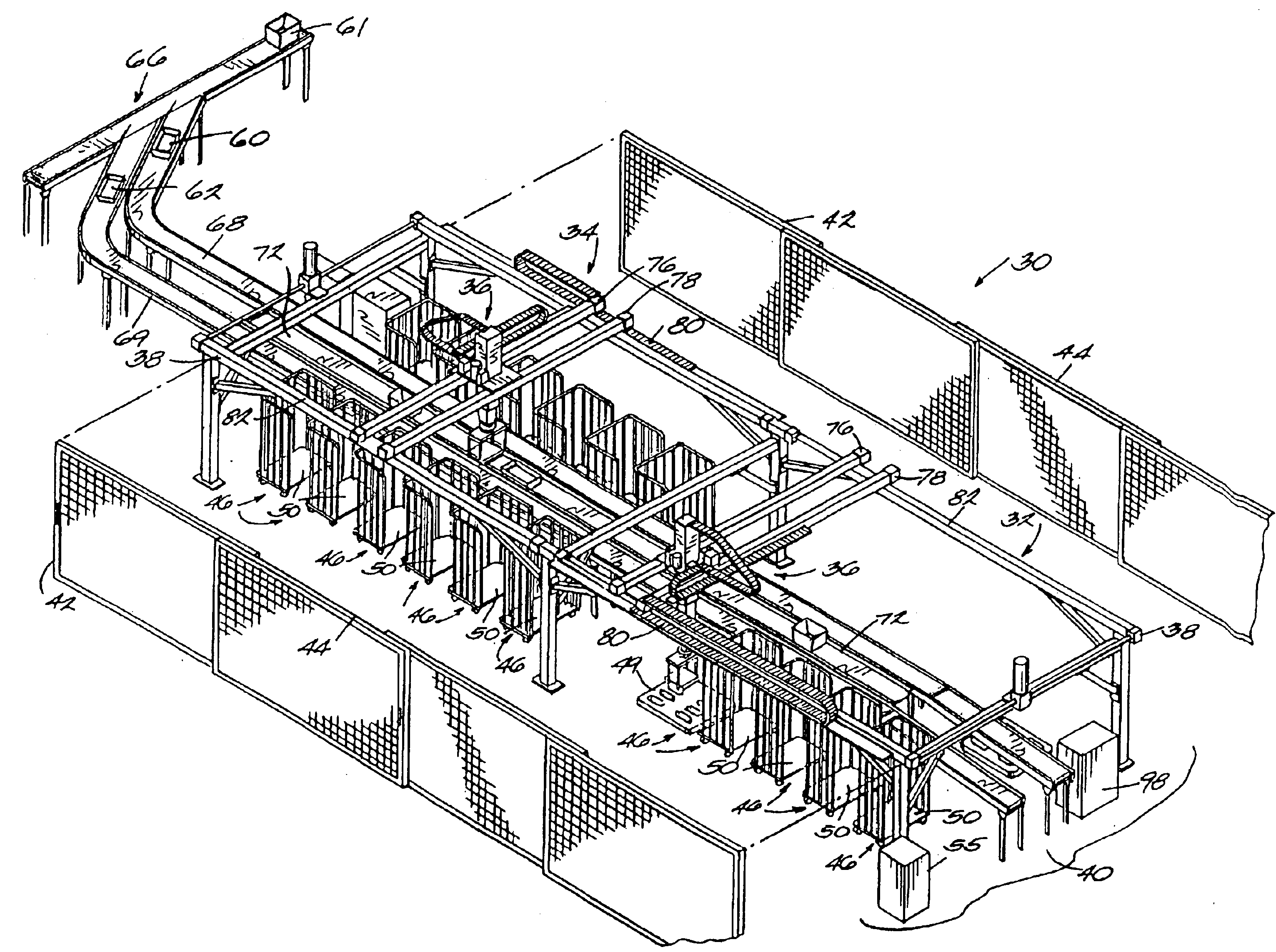
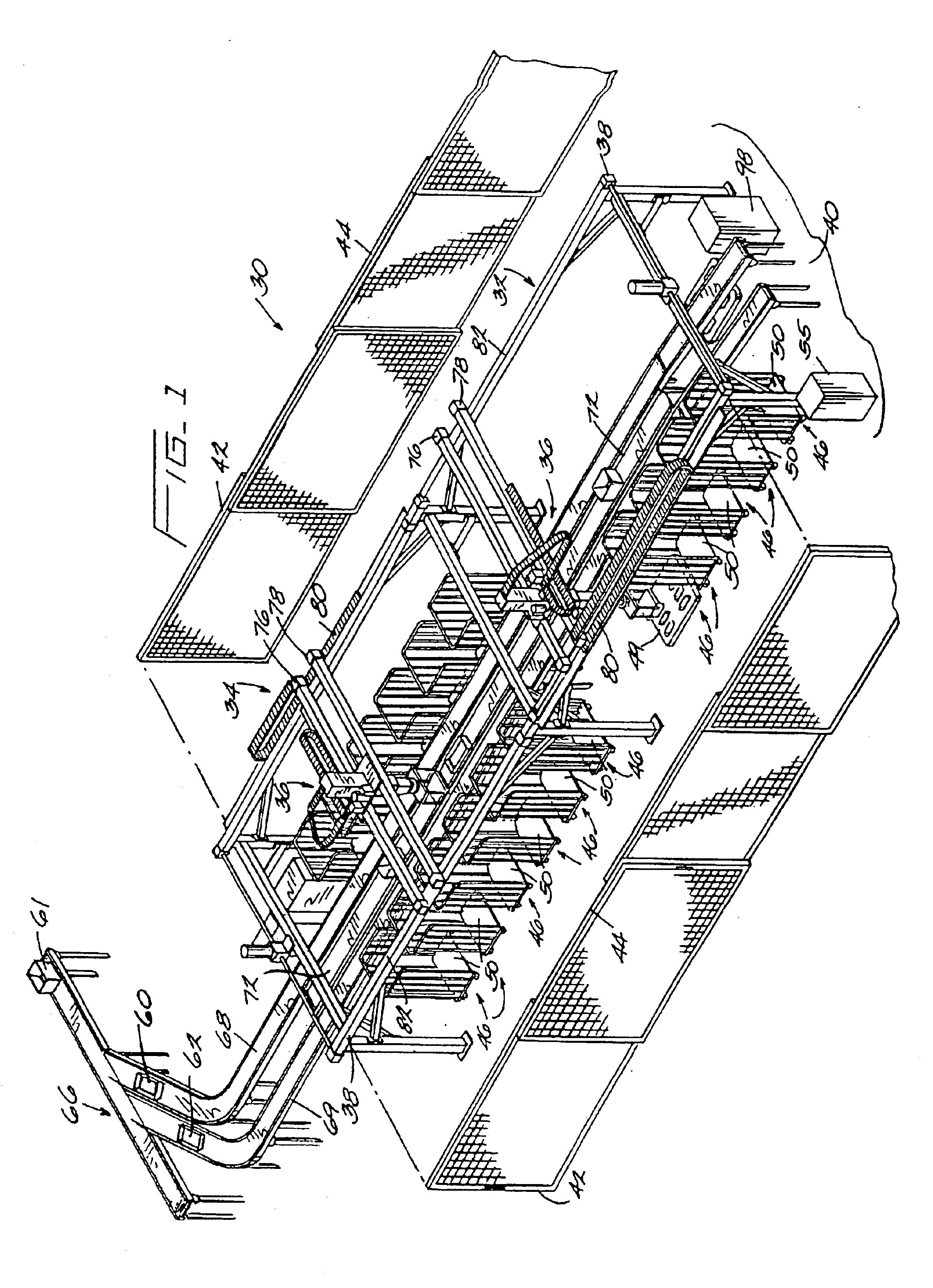
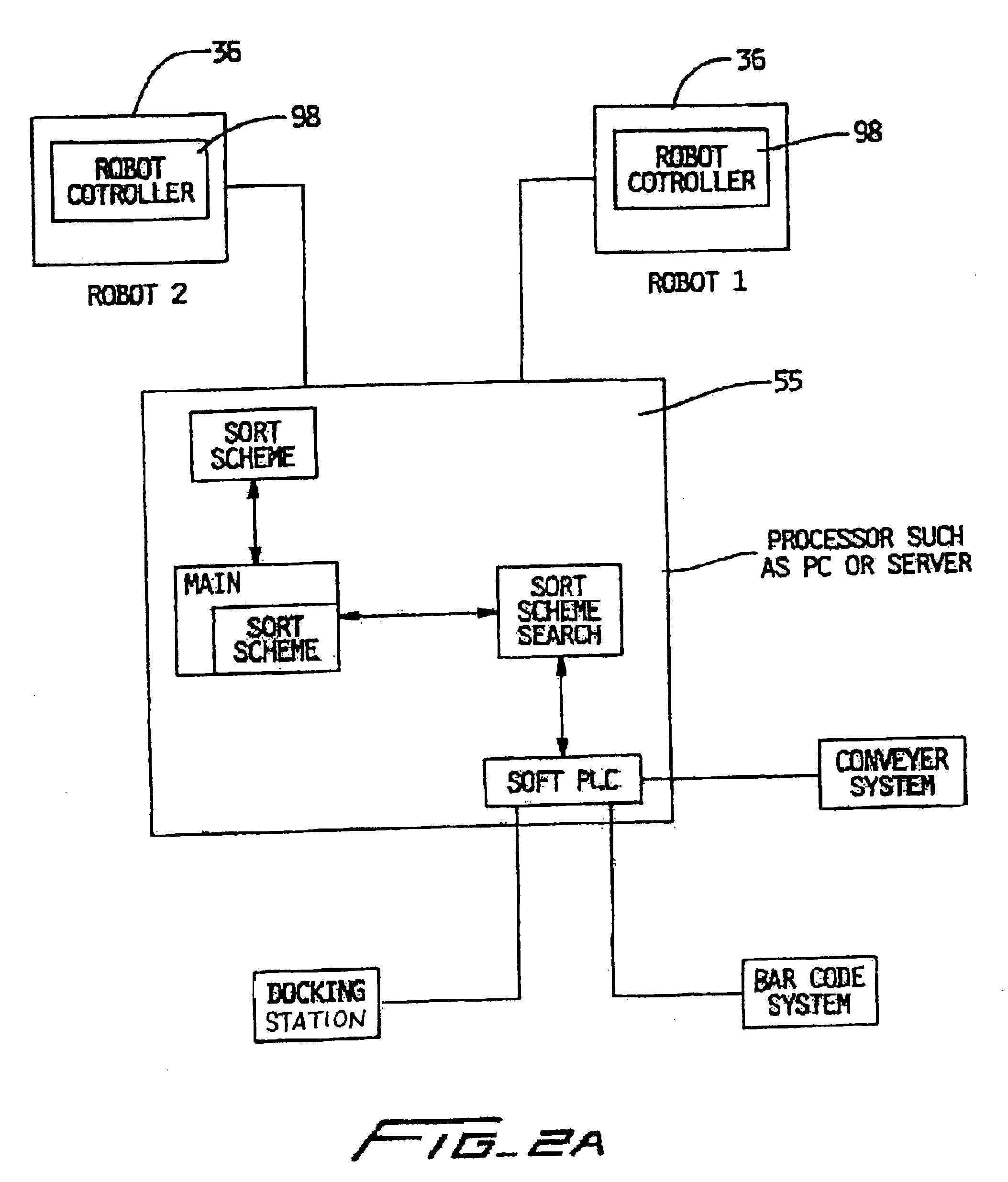
A containerization and palletizing system 30 made in accordance with the teachings of the present invention is shown in FIGS. 1 through 3B. The system 30 includes two cells 32 and 34 each equipped with a gantry or overhead-type robot 36, although the invention may be implemented with just one cell and one robot as well as other types of robots. Each cell 32, 34 has a frame 38 which may be secured to a hard surface such as a concrete floor 40. The space between the frame members may be enclosed with a perimeter fence 42, a mesh, a similar material, or even other types of walls. One or more gates or doors 44 may be provided to permit access to the interior of the cell. Each cell 32, 34 has a plurality of places or bays 46 for pallets 49 and carts 50. Sensors (not shown) sense the presence or absence of pallets 48 and carts 50 (generically referred to as a “containers”) in a bay and that information is communicated to a system controller 55 (described further below). Pallets and carts ...


PUM


Abstract

A robotic containerization and palletizing system having a multiple-fingered end effector. In one embodiment, the system carries out a method of loading a tray in a container where the method includes creating a cell with a plurality of bays; assigning each bay a location; moving trays through the cell along a path; grasping a tray off the path with a robot positioned above the path; moving the robot, with the grasped tray, to the location of one bay; and instructing the robot to release the tray at the location of the one bay.

Description

FIELD OF THE INVENTIONThe present invention relates to systems and devices used to load containers and pallets. More particularly, the present invention relates to a robotic system used to load mail trays and tubs of different shapes and sizes on pallets and into wheeled containers and carts.BACKGROUND OF THE INVENTIONMillions of pieces of mail are deposited with the postal service every day. The deposited mail is sorted, generally by zip or other code, and shipped to the proper destination. Generally, the sorting process involves placing mail with the same or related codes into tubs or trays. Thus, each tub or tray will contain mail addressed to geographically proximate locals. The tubs and trays are then placed on pallets and carts and the pallets and carts are loaded on trucks or other vehicles for shipment to their appropriate destinations.Some parts of this process have been automated, including the sorting of mail by zip code. However, the loading of tubs and trays onto pallet...

Claims


Application Information

Patent Timeline
Patent Type & Authority Patents(United States)
IPC IPC(8): B25J15/10B65G61/00B65G47/90B25J5/00B25J9/00B25J19/02B65B5/08B65B35/16B65B43/42
CPCB25J15/10B65G47/90B65G61/00Y10S209/90Y10S414/106
Inventor GRAMS, ROBERT S.WATSON, THOMASRESCH, PATRICKDOMINGUEZ, GILBERT
Owner ABB FLEXIBLE AUTOMATION INC
Why Eureka
Try Eureka