
Gypsum board forming device

a technology of forming device and gypsum board, which is applied in the direction of turning machine accessories, drawing profiling tools, turning machines, etc., can solve the problems of reducing the edge reducing the strength of the board, and compromising the optimization between cost and effectiveness concerns

Inactive Publication Date: 2005-03-15
BPB LTD
View PDF60 Cites 59 Cited by
  • Summary
  • Abstract
  • Description
  • Claims
  • Application Information

AI Technical Summary

Problems solved by technology

This is a particular problem at the edge margins of the board where the bottom mat is brought up and onto the upper surface of the board to define the edges of the uncut board.
Inefficient exhaustion of air in this region can lead to voids in the edge margins of the cut boards, reducing the edge strength of the boards.
The problem of voids in the edge margins has been dealt with by increasing the fiber diameter of the mat, particularly the bottom mat (to, for example, 16 μm (0.0065 inch)), allowing easier exhaustion of air and penetration of gypsum slurry, but which consequently may result in a reduction of board strength.
Additional compromises in optimization between concerns of cost and of effectiveness arise from the amount of penetration of slurry through the glass mat fibers.
It has been found that when gypsum boards with exposed glass fibers, such as those taught, for example in U.S. Pat. Nos. 4,647,496; 4,810,659; 5,371,989; 5,148,645; 5,319,900; and 5,704,179, are handled at a construction site by workers, exposed glass fibers penetrate the skin of uncovered hands, and this generally results in worker discomfort.
Manufacturing facilities for the production of gypsum board, whether or not glass mats are utilized for the structural facings, are capital intensive in the costs of space, equipment and in the down time during which a gypsum board production line is reconfigured.
For production of a variety of gypsum board products, for example, standard paper faced gypsum board, glass mat backed board, etc., down time of the production line represents a significant cost in the delay of production of gypsum board and in time wasted by production workers who remain idle.
To perform the complete process takes a predetermined amount of time, which is an uncompromising restraint on the amount of gypsum board that can be processed on a gypsum board line.
Additional compromises in optimization between concerns of cost and effectiveness arise from the amount of penetration of slurry through the mineral or glass mat fibers when these are utilized as facing materials.
It has been found that when gypsum boards with exposed glass fibers, such as those taught, for example, in U.S. Pat. Nos. 4,647,496; 4,810,569; 5,371,989; 5,148,645, 5,319,900; and 5,704,179, are handled at a construction site by workers, glass fibers penetrate the skin of uncovered hands and result in discomfort.
Although the smooth surface of gypsum boards provided by the process utilized in aforementioned U.S. Pat. No. 4,378,405 is adequate to achieve the stated purposes, the process of manufacture, and especially the vibration steps, tend to slow down board production operation and to render the process useful only for specialized applications for which a customer is willing and able to contend with delays in production and in the consequential costs.
Moreover, it is not possible to utilize the process of making GRG gypsum boards as taught by U.S. Pat. No. 4,378,405 in a standard gypsum board line because that process requires structural changes to the board production line, which may take time and capital to effectuate.
The need to allow sufficient time for the gypsum slurry to penetrate through the mat also restricts the speed of the gypsum board manufacturing line.

Method used


Image

  • Gypsum board forming device
  • Gypsum board forming device
  • Gypsum board forming device

Examples


Embodiment Construction

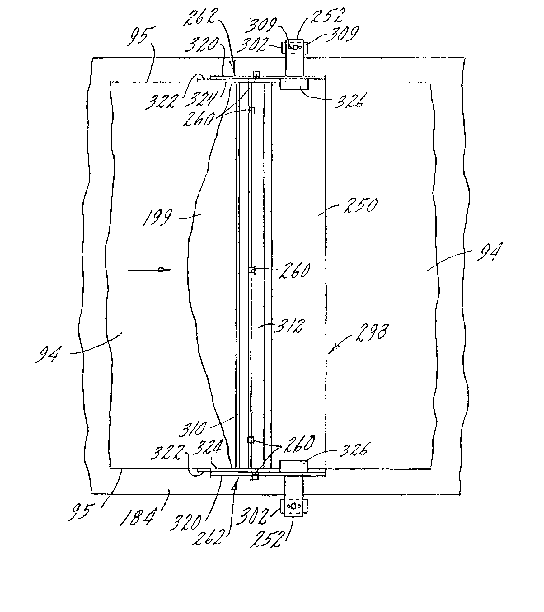
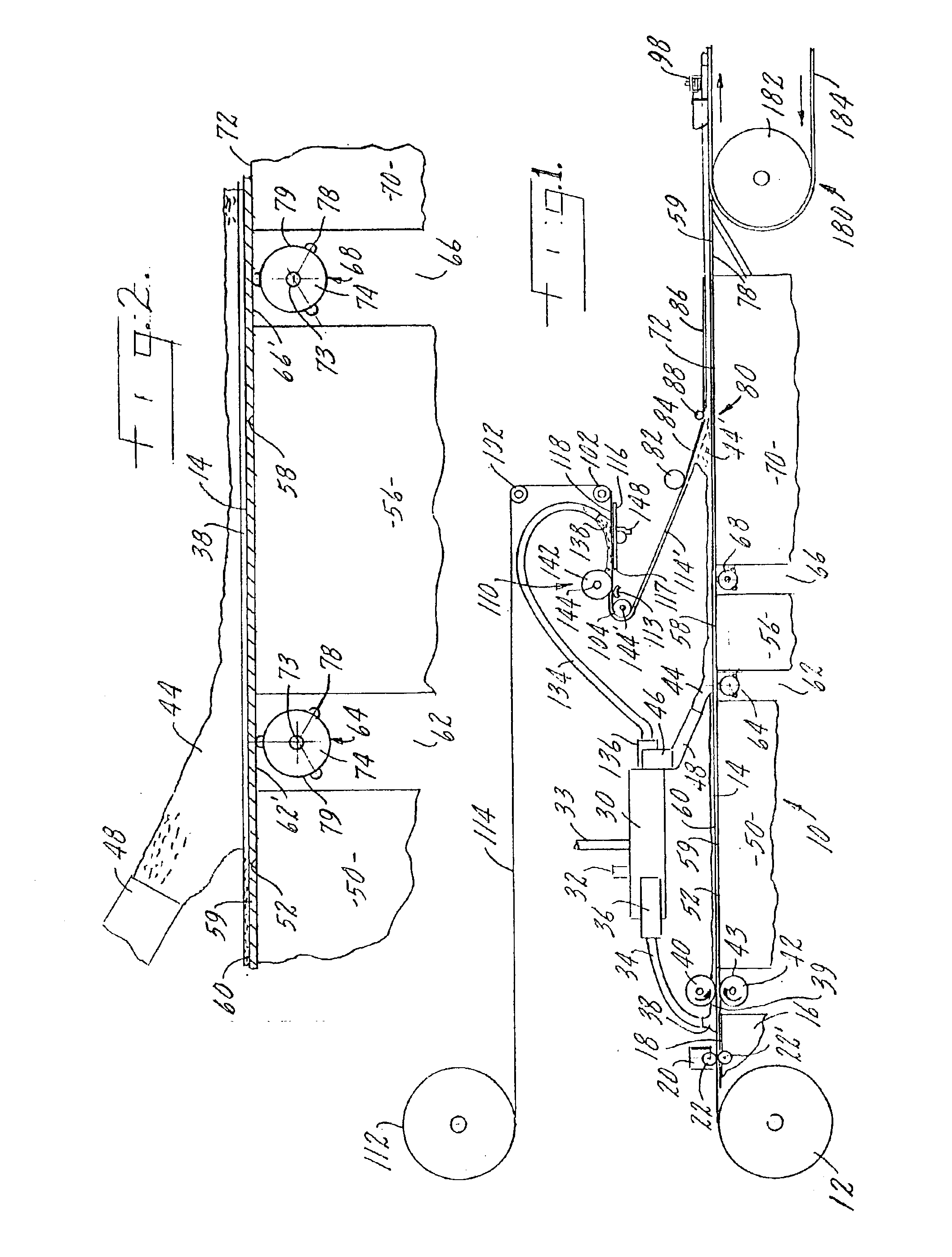
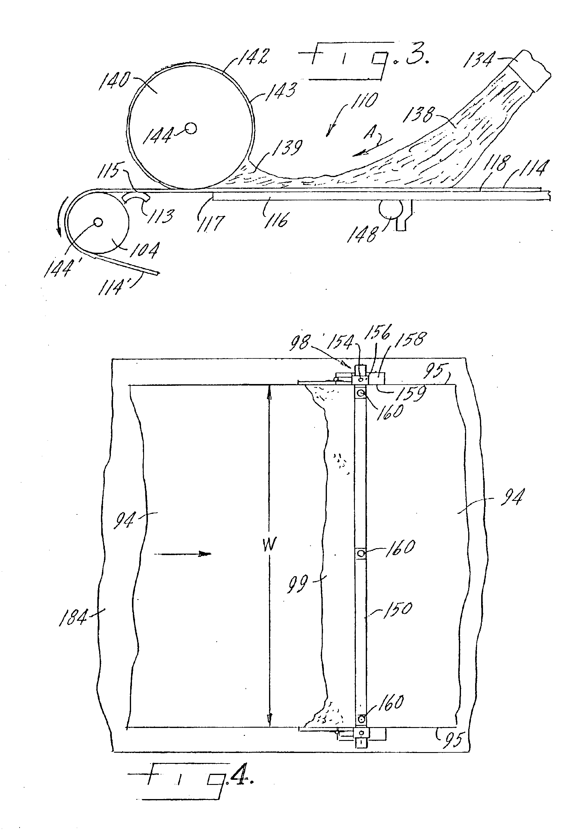
In the diagrammatical, cross-sectional illustration of FIG. 1, the board forming station 10 of an inventive embodiment of the inventive plant is shown. Although illustrated in cross section, the station 10 is shown diagrammatically to clearly depict the separate elements in relation to each other. Modifications to the arrangement are possible and distances between the separate elements are not to scale for simplicity of illustration, but a pragmatic and efficient arrangement will come to mind to a person having ordinary skill in the art.

The inventive plant 10 comprises a supply roll 12 that provides feed of a continuous sheet of facing material that, in the arrangement shown, defines a bottom-facing sheet 14. The supply roll 12 may feed out a sheet comprising any conventional material used in gypsum boards, for example, paper or paper board, but for purposes of the present invention, the material of bottom facing sheet 14 preferably comprises a mat of long inorganic, e.g., glass, fi...


PUM

PropertyMeasurementUnit
angleaaaaaaaaaa
angleaaaaaaaaaa
diameteraaaaaaaaaa

Abstract

A gypsum board forming device having a gypsum forming station including two laterally disposed edger shoes, and at least one laterally disposed edger bar clamping element on the edger bar. In one embodiment a laterally extending forming plate extends over the top surface of the formed gypsum board, the forming plate including a plurality of micropore conduits through which pressurized water is supplied to provide a film of smoothing water over the top surface of the gypsum board. In another embodiment the edger shoes have a flapper mechanism for retaining unset slurry skimmed off the surface of the gypsum board by the edger bar.

Description

BACKGROUND OF THE INVENTION1. Field of the InventionThis invention relates generally to gypsum board and its manufacture, and more specifically, relates to gypsum board having at least one face or surface capable of receiving and adhering to polymeric coatings and that is manufactured quickly and efficiently.2. Background ArtGypsum board, and its production, has received attention in the building industry, and especially for providing an easily worked building material the consistency of which is available for general construction use. Desirable characteristics for gypsum board also include a smooth working surface, consistent thickness throughout, and the ability to provide finishing enhancements, such as paint or other protective coverings, thereon.Recent developments in the manufacture of gypsum board have also added to the durability and versatility of the uses to which gypsum boards may be put.A particularly useful development in the building board field is known as glass reinf...

Claims


Application Information

Patent Timeline
Patent Type & Authority Patents(United States)
IPC IPC(8): B32B13/02B32B13/00B28B11/08B28B19/00E04C2/04
CPCB28B11/0845B28B19/0092B32B13/02E04C2/043Y10T428/22Y10T156/1011Y10T156/1043Y10T428/23Y10T428/239Y10T156/1034Y10T428/237Y10T428/232B32B2260/044B32B2260/021B32B2607/00
Inventor HAUBER, ROBERT J.SANDERS, CHRISTOPHER J.HENNIS, MARK E.FAHEY, MICHAEL P.
Owner BPB LTD
Learn More