Rotary blood pump and control system therefor

a technology of rotary pumps and control systems, which is applied in the direction of prosthesis, liquid fuel engines, therapy, etc., can solve the problems of rotors of motors providing shaft torque that remain to be supported, and the seal needed on the shaft may leakag

Inactive Publication Date: 2005-03-15
TC1 LLC +1
View PDF32 Cites 176 Cited by
  • Summary
  • Abstract
  • Description
  • Claims
  • Application Information

AI Technical Summary

Benefits of technology

In yet a further broad form of the invention there is provided a physiological controller for use in association with a pump; said controller monitoring estimated flow of fluid within said pump and pressure across said pump by non-contact means thereby to control speed of rotation of an impeller within said pump; and wherein said controller permits impeller speed to vary under a pulsating fluid load thereby to assist in calculation and adjustment of impeller speed set point.
Preferably variation in speed of said impeller, in use, is utilized to calculate an estimate of said operating point to an improved level of accuracy.

Problems solved by technology

Several of these characteristics are very difficult to meet in a conventional pump configuration including a seal, i.e. with an impeller mounted on a shaft which penetrates a wall of the pumping cavity, as exemplified by the blood pumps referred to in U.S. Pat. No. 3,957,389 to Rafferty et al., U.S. Pat. No. 4,625,712 to Wampler, and U.S. Pat. No. 5,275,580 to Yamazaki.
Two main disadvantages of such pumps are firstly that the seal needed on the shaft may leak, especially after wear, and secondly that the rotor of the motor providing the shaft torque remains to be supported, with mechanical bearings such as ball-bearings precluded due to wear.
Contact or pivot bearings, as exemplified by U.S. Pat. No. 5,527,159 to Bozeman et al. and U.S. Pat. No. 5,399,074 to Nose et al., have potential problems due to wear, and cause very high localised heating and shearing of the blood, which can cause deposition and denaturation of plasma proteins, with the risk of embolisation and bearing seizure.
Position measurement and feedback control introduce significant complexity, increasing the failure risk.
Power use by the control current implies reduced overall efficiency.
Furthermore, size, mass, component count and cost are all increased.
U.S. Pat. No. 5,507,629 to Jarvik claims to have found a configuration circumventing Earnshaw's Theorem and thus requiring only passive magnetic bearings, but this is doubtful and contact axial bearings are included in any case.
It does not disclose an exclusively hydrodynamically suspended impeller within a pump.
It does not disclose a hydrodynamically suspended impeller, much less an exclusively hydrodynamically suspended impeller within a pump.
It would be inefficient to pass all the fluid through the bearing gap, of small cross-sectional area, as this would demand an excessive pressure drop across the bearing.

Method used


Image

  • Rotary blood pump and control system therefor
  • Rotary blood pump and control system therefor
  • Rotary blood pump and control system therefor

Examples


third embodiment

With reference to FIGS. 7 to 15 inclusive there is shown a further preferred embodiment of the pump assembly 200.

With particular reference initially to FIG. 7 the pump assembly 200 comprises a housing body 201 adapted for bolted connection to a housing cover 202 and so as to define a centrifugal pump cavity 203 therewithin.

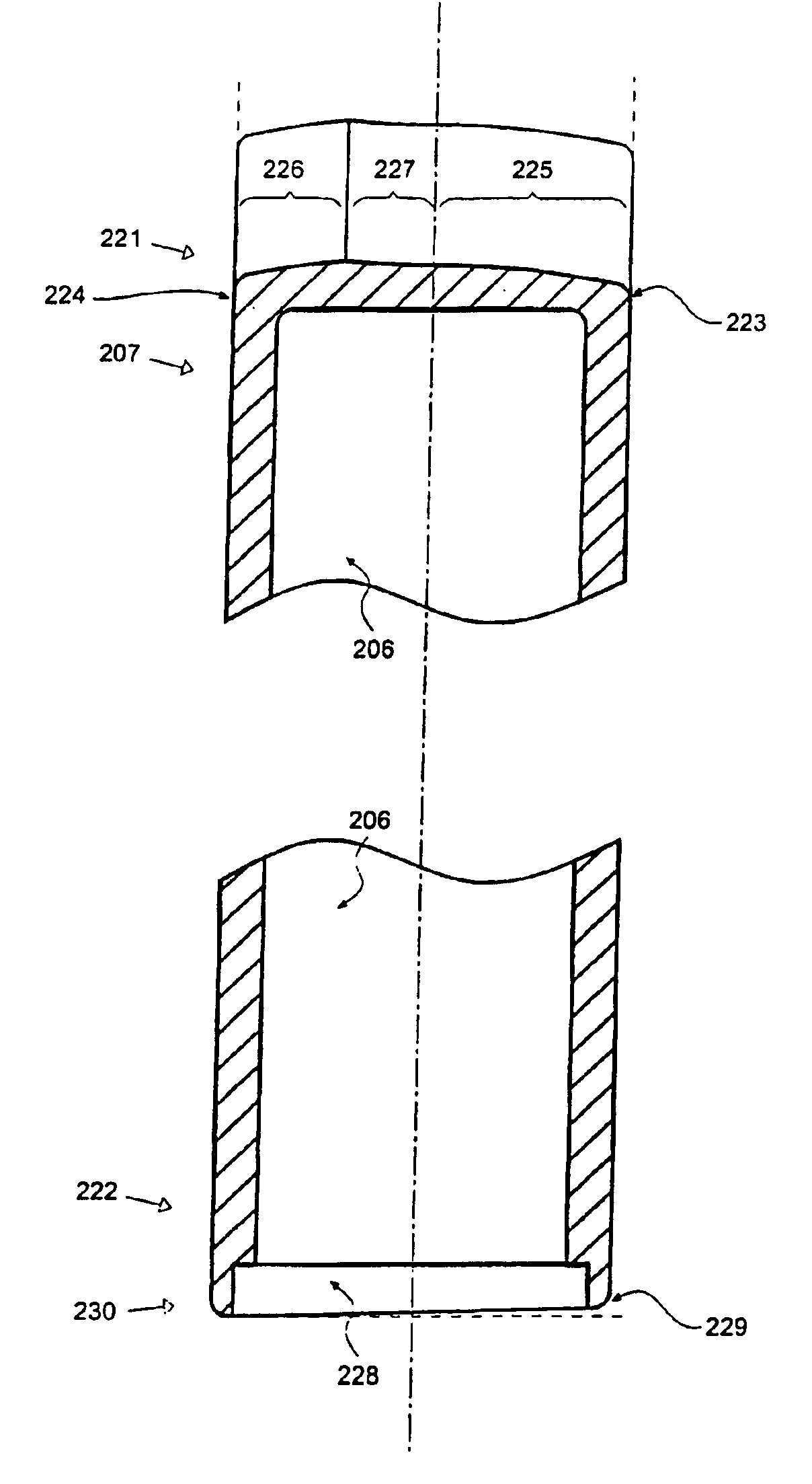
The cavity 203 houses an impeller 204 adapted to receive magnets 205 within cavities 206 defined within blades 207. As for the first embodiment the blades 207 are supported from a support 208.

Exterior to the cavity 203 but forming part of the pump assembly 200 there is located a body winding 209 symmetrically mounted around inlet 210 and housed between the housing body 201 and a body yoke 211.

Also forming part of the pump assembly 200 and also mounted external to pump cavity 203 is cover winding 212 located within winding cavity 213 which, in turn, is located within housing cover 202 and closed by cover yoke 214.

The windings 212 and 209 are supplied from the elect...

fourth embodiment

With reference to FIG. 18 a further embodiment of the invention is illustrated comprising a plan view of the impeller 300 forming part of a “channel” pump. In this embodiment the blades 301 have been widened relative to the blades 207 of the third embodiment to the point where they are almost sector-shaped and the flow gaps between adjacent blades 301, as a result, take the form of a channel 302, all in communication with axial cavity 303.

A further modification of this arrangement is illustrated in FIG. 19 wherein impeller 304 includes sector-shaped blades 305 having curved leading and trailing portions 306, 307 respectively thereby defining channels 308 having fluted exit portions 309.

As with the first and second embodiments the radial and axial hydrodynamic forces are generated by appropriate profiling of the top and bottom faces of the blades 301, 305 (not shown in FIGS. 18 and 19).

FIG. 20 illustrates a perspective view of an impeller 304 which follows the theme of the impeller a...

fifth embodiment

A fifth embodiment of a pump assembly according to the invention comprises an impeller 410 as illustrated in FIG. 21 where, conceptually, the upper and lower surfaces of the blades of previous embodiments are interconnected by a top shroud 411 and a bottom shroud 412. In this embodiment the blades 413 can be reduced to a very small width as the hydrodynamic behaviour imparted by their surfaces in previous embodiments is now given effect by the profiling of the shrouds 411, 412 each of which, in this instance, comprise a series of smoothed wedges 414 with the leading edge of one wedge directly interconnected to the trailing edge of the preceding wedge.

As for previous embodiments the top shroud 411 is of overall conical shape thereby to impart both radial and axial thrust forces whilst the bottom shroud 412 is substantially planar thereby to impart substantially only axial thrust forces.

It is to be understood that, whilst the example of FIG. 21 shows the surfaces of the shroud 411 ang...


PUM


Abstract

A pump assembly and estimation and control system therefor, the pump adapted for continuous flow pumping of blood. In a particular form, the pump is a centrifugal pump wherein the impeller is entirely sealed within the pump housing and is exclusively hydrodynamically suspended therein against movement in three translational and two rotational degrees of freedom as the impeller rotates within the fluid urged by electromagnetic means external to the pump cavity. Hydrodynamic suspension is assisted by the impeller having deformities therein such as blades with surfaces tapered from the leading edges to the trailing edges of bottom and top surfaces thereof.

Description

FIELD OF THE INVENTIONThis invention relates to rotary pumps adapted, but not exclusively, for use as artificial hearts or ventricular assist devices and, in particular, discloses in preferred forms a seal-less shaft-less pump featuring open or closed (shrouded) impeller blades with at least parts of the impeller used as hydrodynamic thrust bearings and with electromagnetic torque provided by the interaction between magnets embedded in the blades or shroud and a rotating current pattern generated in coils fixed relative to the pump housing.In addition, a non-contact estimation and control system is described for use in conjunction with the rotary pumps of the invention.BACKGROUND ARTThis invention relates to the art of continuous or pulsatile flow rotary pumps and, in particular, to electrically driven pumps suitable for use although not exclusively as an artificial heart or ventricular assist device. For permanent implantation in a human patient, such pumps should ideally have the ...

Claims


Application Information

Patent Timeline
Patent Type & Authority Patents(United States)
IPC IPC(8): A61M1/10
CPCA61M1/101A61M1/1015A61M1/1031A61M1/1017Y10S415/90A61M2205/3334A61M60/824A61M60/422A61M60/148A61M60/232A61M60/237A61M60/178A61M60/221
Inventor AYRE, PETER JOSEPHTANSLEY, GEOFFREY DOUGLASWATTERSON, PETER ANDREWWOODARD, JOHN CAMPBELL
Owner TC1 LLC
Why Eureka
Try Eureka