Determination of finger position

Inactive Publication Date: 2005-03-15
IMMERSION CORPORATION
View PDF83 Cites 42 Cited by
  • Summary
  • Abstract
  • Description
  • Claims
  • Application Information

AI Technical Summary

Benefits of technology

Typical PSE sensing technologies include but are not limited to Global Positioning Systems (GPS), Hall Effect and other magnetic and electromagnetic technologies; ultrasonics using time of flight and/or phase information and other acoustic technologies; CCD cameras, lateral effect photodiodes, infrared emitters and detectors and other light-based and optical

Problems solved by technology

Up to now no one has accomplished this goal.
Even if it were technically possible, suc

Method used


Image

  • Determination of finger position
  • Determination of finger position
  • Determination of finger position

Examples


Embodiment Construction

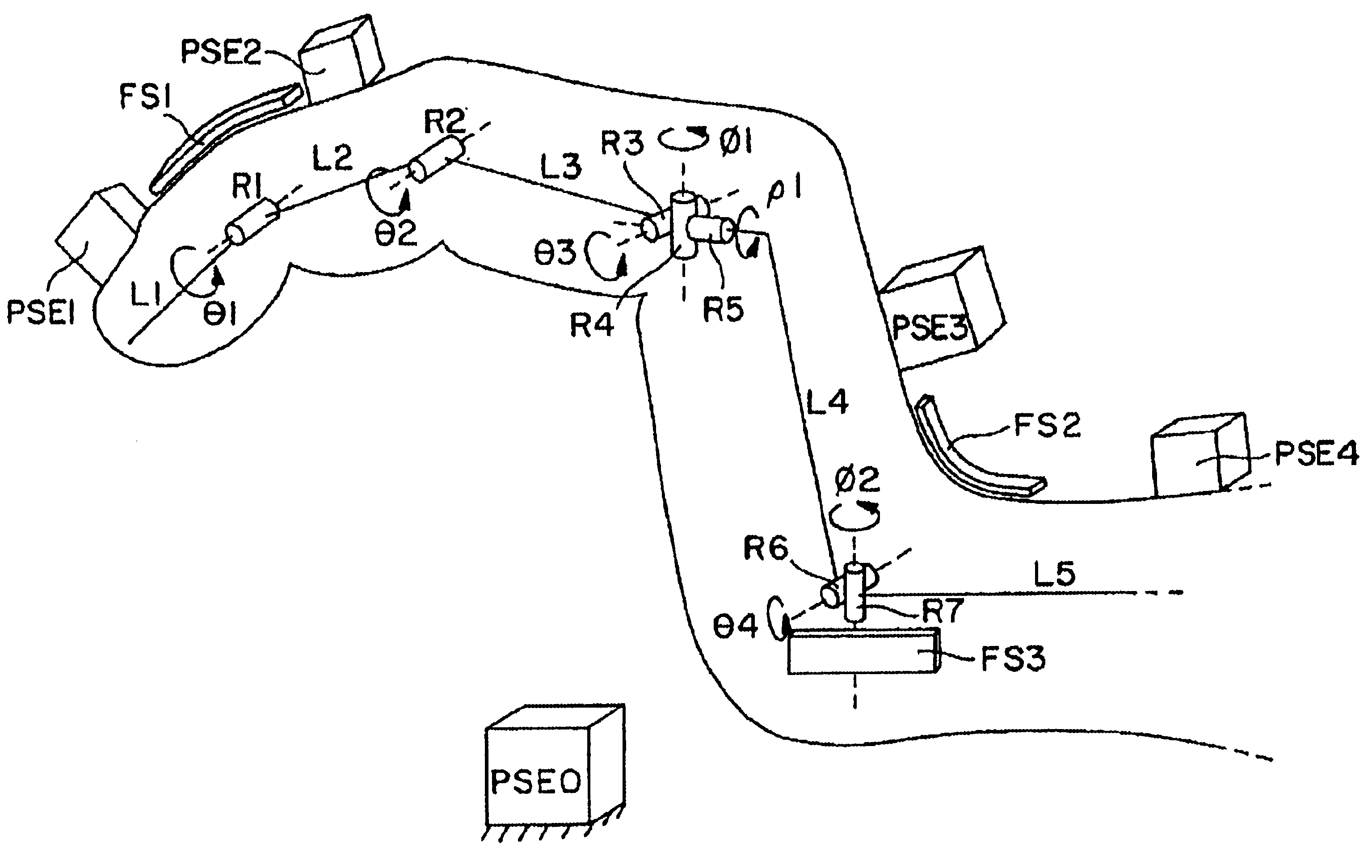
In general, the subject invention provides means for determining the spatial placement of a plurality of human or other living being body-parts. In particular, the subject invention provides means for measuring and determining the spatial placement of a human hand system including various elements of the hand, wrist and forearm.

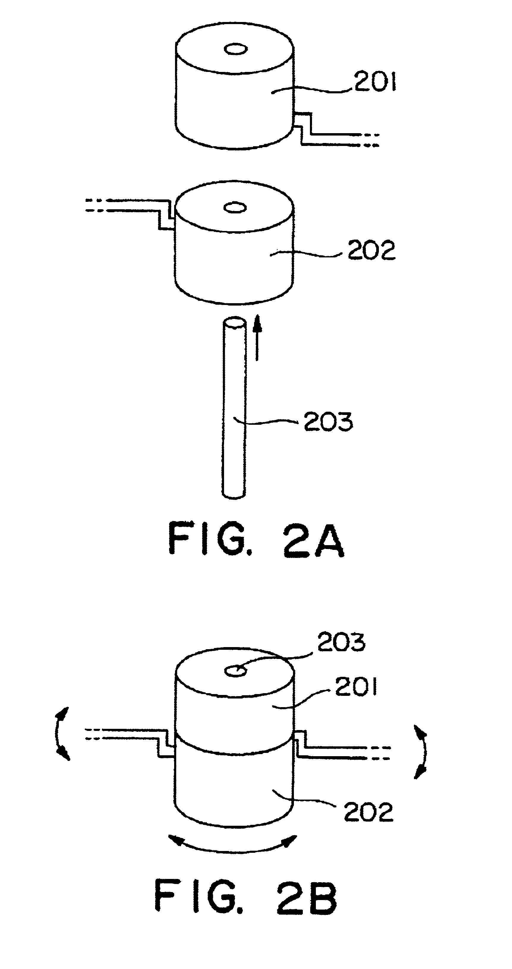
Referring now specifically to the drawings, FIGS. 2A and 2B show enlarged views of a model for a revolute joint. A revolute joint is depicted as a cylindrical joint having two cylindrical hinged elements 201, 202 and a coaxial axis of rotation, where one hinged element is capable of rotating about the axis relative to the other hinged element. In FIGS. 2A and 2B the top 201 and bottom 202 portions of the cylinder may rotate about the axis 203 relative to each other. When more than one rotary degree-of-freedom (DOF) is specified at a single location, multiple cylinders are drawn, one cylinder per DOF. Except when indicated otherwise, when two revolute joint cy...


PUM


Abstract

A prescription is provided which specifies constraints, e.g., the type (revolute and/or prismatic) and the number of joints which may be included between any two position-sensing elements (PSEs), where the joints connect the links of a kinematically constrained multi-articulated structure, whereby the defining parameters of the structure may be determined using the spatial placement of the two PSEs and the kinematic constraints of the multi-articulated structure, and where at least the spatial placement of one link is not directly measured. Also provided are preferred placements of PSEs and goniometers on a kinematically constrained multi-articulated structure which will allow determination of the spatial placement of the links, where at least the spatial placement of one link is not directly measured. Revolute joint models of the articulations of the entire human body, as well as preferred PSE and goniometer locations, are provided. An algorithm is provided for determining the joint angles for a finger modeled as a 4-link planar manipulator with one PSE affixed to the fingertip and one PSE affixed to the metacarpus.

Description

Absolute position sensing means has existed for a number of years. In particular, an absolute position sensing technology based on electromagnetic (E / M) sensing has been commercially available since the mid 1970's and comprises two sets of three orthogonally wound coils. One set of three coils is used as the E / M transmitter (Tx) while the other set of three coils is used as the receiver (Rx). One manufacturer of such an E / M system, Polhemus, Inc., drives each of the transmitter coils sequentially at a known frequency, while another manufacturer, Ascension Technology Corp., drives each transmitter coil in pulsed mode. Each receiver coil acts as an antenna and picks up the transmitted E / M signal. Mathematically speaking, driving the coils in this manner produces data for 9 equations (1 equation for each transmitter / receiver coil pair), where there are only 6 unknowns (x, y, z, azimuth, elevation and roll). The 6 unknowns can be determined, to the extent that the sensor may lie in eith...

Claims


Application Information

Patent Timeline
IPC IPC(8): A61B5/103B25J13/08B25J13/02G01S13/87G01S13/00G01S13/75G06F3/00G06F3/01
CPCA61B5/103A61B5/4528A61B5/6806A61B5/6807A61B5/6814A61B5/6826A61B5/6831A61B5/6838B25J13/02B25J13/088G01S13/753G01S13/874G06F3/011G06F3/016A61B5/1071A61B5/6825A61B2562/043A61B2562/046A61B5/6823A61B5/6824
Inventor KRAMER, JAMES F.
Owner IMMERSION CORPORATION
Why Eureka
Try Eureka