Blue phosphor for fluorescent display and method for synthesizing the same

a fluorescent display and blue phosphor technology, applied in the field of display technology, can solve the problems of only scanning electrons, affecting the state of phosphor, and poor luminous efficiency and color purity at low voltage, and achieves the effects of reducing production costs, high luminescence, and maintaining panel performan

Inactive Publication Date: 2005-03-15
PENDRAGON ELECTRONICS & TELECOMM RES
View PDF2 Cites 1 Cited by
  • Summary
  • Abstract
  • Description
  • Claims
  • Application Information

AI Technical Summary

Benefits of technology

According to the blue phosphor of the present invention, when it is applied to a fluorescent display or used as an anode plate of an FED phosphor, it can prevented from being destructed due to prolonged scanning time so that the degree of vacuum between the cathode plate and the anode plate can be maintained, thereby maintaining the panel performance for a long time of period. Also, since the synthesis temperature of the blue phosphor for a fluorescent display according to the present invention is lower than that of the conventional phosphor, the production cost can be remarkably reduced while exhibiting high luminescence. Therefore, when the blue phosphor according to the present invention is applied to a fluorescent display, it can exhibit good characteristics such as high luminescence or high definition and can make a large contribution to commercialization of low voltage FEDs.

Problems solved by technology

However, if the electronic energy is as low as 1 kV or less, electrons can only be scanned as deep as 20 nm from a phosphor surface.
Also, the surface state of a phosphor greatly affect the luminous efficiency thereof.
In particular, when a conventional sulfide blue phosphor, ZnS: Ag, Al, which has been widely used in CRTs, is used as an FED phosphor, it exhibits bad luminous efficiency and color purity at low voltages.
Also, prolonged E-beam scanning gives rise to desorption of a trace of sulfur from sulfide-based phosphors, resulting in a decrease in the internal vacuum degree for smaller volume in the case where the distance between a cathode plate and an anode plate is approximately 1 mm like in an FED panel or impairing an FEA, thereby deteriorating display performance.
In current actuality, the major factor in the processing cost is the firing temperature in the course of synthesis.

Method used


Image

  • Blue phosphor for fluorescent display and method for synthesizing the same
  • Blue phosphor for fluorescent display and method for synthesizing the same
  • Blue phosphor for fluorescent display and method for synthesizing the same

Examples


Embodiment Construction

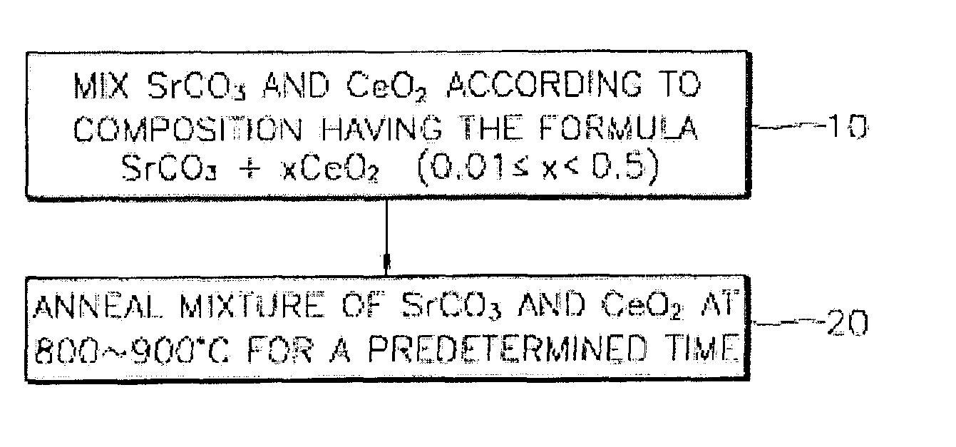
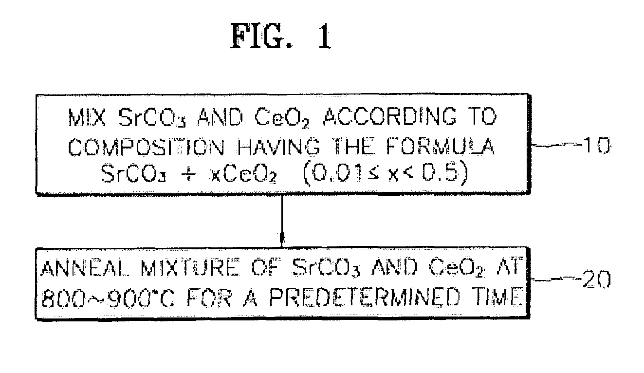
FIG. 1 is a flow chart for explaining a method for synthesizing a blue phosphor for a fluorescent display according to a preferred embodiment of the present invention.

Referring to FIG. 1, a mixture having strontium carbonate (SrCO3) as a host and cerium oxide (CeO2) as an activator homogenously mixed is prepared (step 10). To this end, strontium carbonate (SrCO3) and cerium oxide (CeO2) are put into a mortar containing alcohol as a solvent according to the composition having the following general formula, followed by homogenously mixing and drying:

SrCO3+xCeO2

wherein 0.01≦x≦0.5.

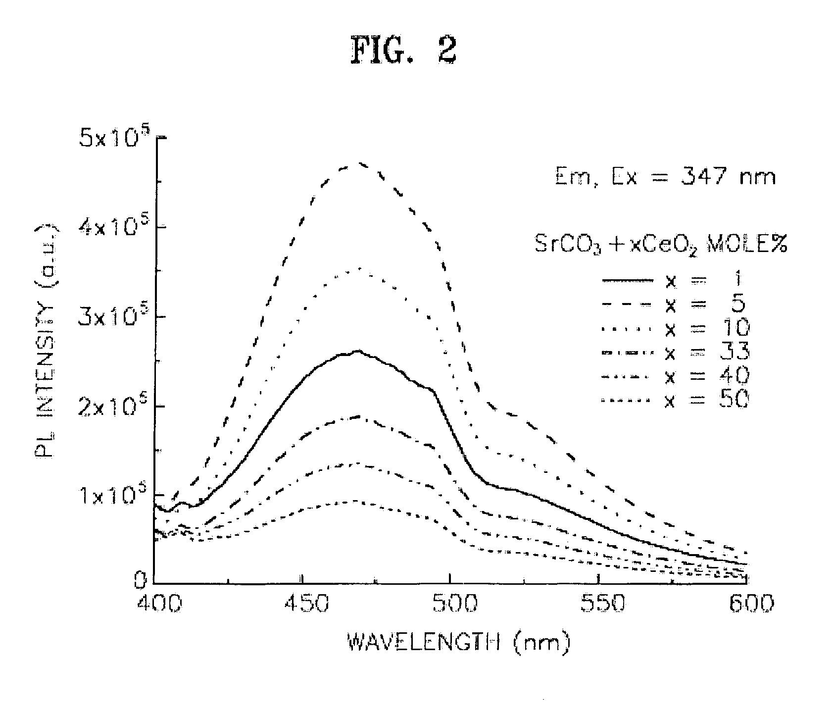
Thereafter, the resultant dried mixture obtained in step 10 is put into an alumina tube and firing at an electric heater maintained at a temperature of approximately 800 to 900° C. for approximately 12 to 36 hours, thereby synthesizing a desired phosphor (step 20).

If the firing temperature exceeds 1000° C., different phase phosphors are generally synthesized. In particular, a sample annealed at 1000° C. is che...


PUM

PropertyMeasurementUnit
voltageaaaaaaaaaa
voltageaaaaaaaaaa
voltageaaaaaaaaaa

Abstract

Provided are a blue phosphor for a fluorescent display having a high luminous efficiency, and a method for synthesizing the same. The blue phosphor is obtained from a host composed of strontium carbonate (SrCO3) and an activator composed of a cerium compound. The method for synthesizing the blue phosphor includes preparing a mixture having strontium carbonate (SrCO3) and a cerium oxide (CeO2) homogenously mixed according to the composition having the following general formula:
SrCO3+xCeO2
wherein 0.01≦x≦0.5, and annealing the mixture at 800 to 900° C.

Description

BACKGROUND OF THE INVENTION1. Field of the InventionThe present invention relates to display technology, and more particularly, to a blue phosphor for a fluorescent display and a method for synthesizing the same.2. Description of the Related ArtFluorescent displays, in particular, field emission displays (FEDs) are flat-panel displays driven by the same operating principle as cathode ray tubes (CRTs), and are constructed such that a cathode plate, which is a field emitter array (FEA) panel emitting electrons by an electric field rather than by thermions, and an anode plate, which is a fluorescent panel receiving electrons to emit light, are a predetermined gap spaced apart and packaged in high vacuum state.Conventional CRTs generally employ sulfide-based phosphors which are good in color purity and luminous efficiency. However, if FEDs, in which a space between a cathode plate and an anode plate is short, use a high voltage of 10 kV or greater like in CRTs, discharge occurs. Thus, F...

Claims


Application Information

Patent Timeline
Patent Type & Authority Patents(United States)
IPC IPC(8): C09K11/77C09K11/08C09K11/55C09K11/65H01J29/20H01J31/12
CPCC09K11/7718C09K11/55
Inventor KANG, SEUNG-YOULSUH, KYUNG-SOO
Owner PENDRAGON ELECTRONICS & TELECOMM RES
Why Eureka
Try Eureka