Optically rebalanced accelerometer

a technology of accelerometer and optical rebalance, applied in the field of accelerometers, can solve the problems of insufficient manufacturing base of electromechanical instruments, relatively large and expensive electromagnetic components, and inability to meet the needs of measurement, and achieve the effects of low power, low weight, and improved accuracy

Inactive Publication Date: 2005-03-15
CHARLES STARK DRAPER LABORATORY
View PDF10 Cites 7 Cited by
  • Summary
  • Abstract
  • Description
  • Claims
  • Application Information

AI Technical Summary

Benefits of technology

The optical accelerometer according to the present invention uses only electrooptical components. The optical accelerometer can therefore be built more economically, as compared to accelerometers based on electromechanical components, by taking advantage of the growing manufacturing base in the fiberoptic communication industry. Further, the projected lifetime of the optical accelerometer according to the present invention is several orders of magnitude greater than the lifetime of accelerometers based on electromechanical components, because the accelerometer has no moving wear surfaces. Finally, because integrated optics and fiberoptics is used, the optical accelerometer according to the present invention is very small, low weight, and low power.

Problems solved by technology

In the past, such sensors have been constructed from relatively large and expensive electromagnetic components.
The manufacturing base for electromechanical instruments is, however, saturated and on the decline.

Method used


Image

  • Optically rebalanced accelerometer
  • Optically rebalanced accelerometer
  • Optically rebalanced accelerometer

Examples


Embodiment Construction

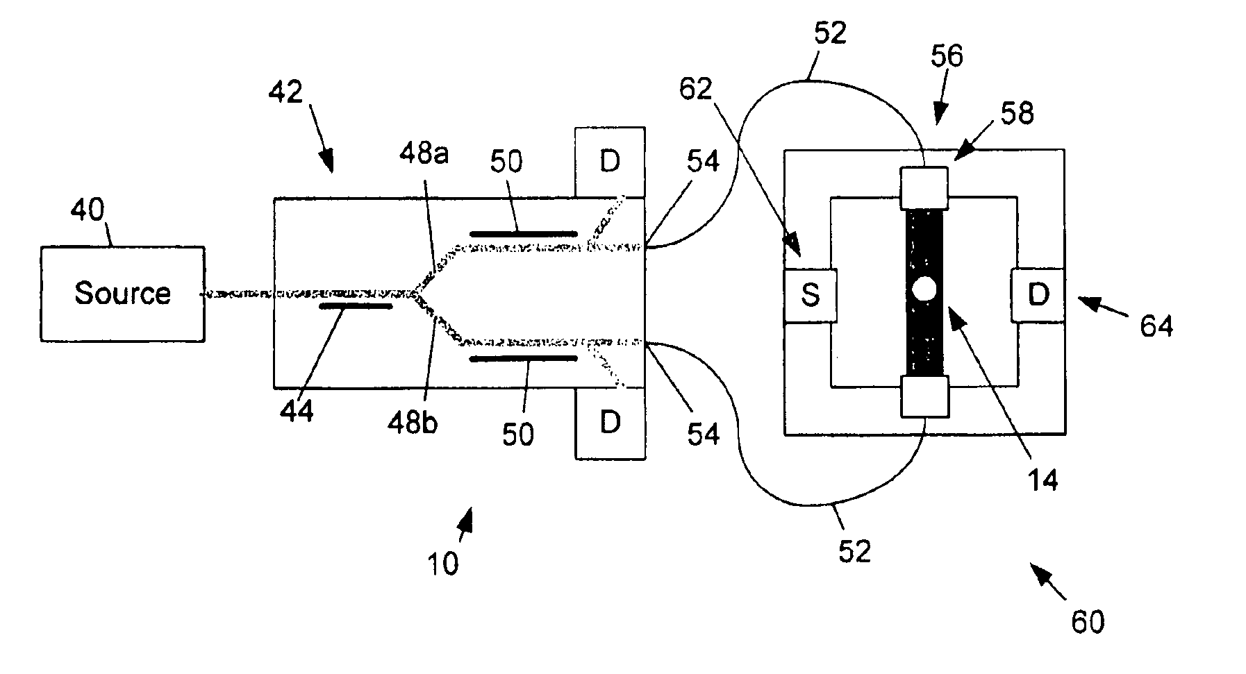
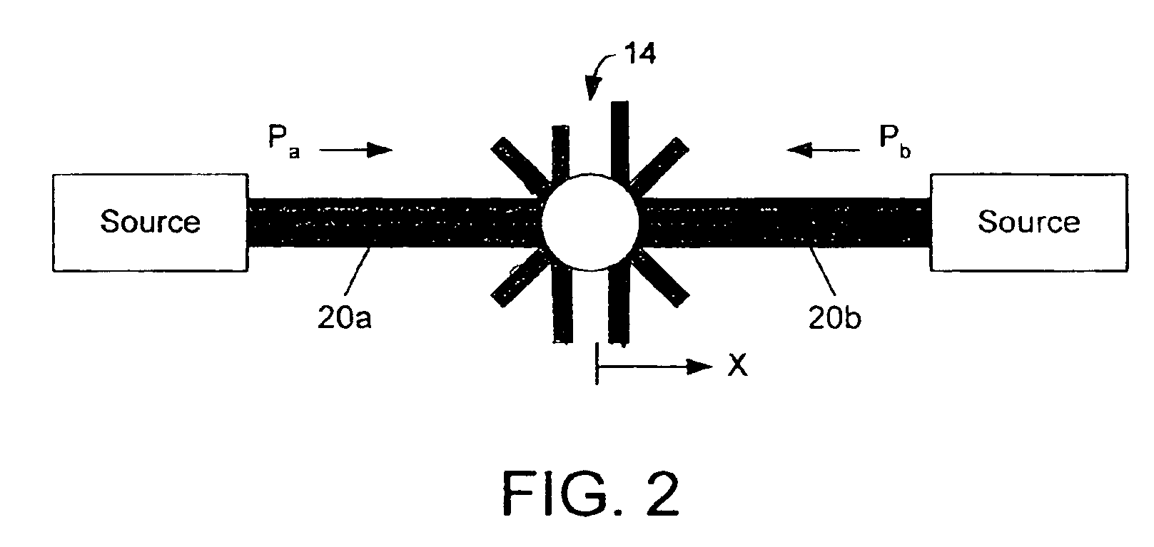
The present invention relates to an all-optical, rebalanced accelerometer that uses radiation pressure to stabilize a proof mass. In overview, an optical accelerometer according to the present invention uses one or more pairs of mutually orthogonal optical beams from an optical source, in order to stabilize a proof mass, using radiation pressure from the optical beams. In response to an inertial force acting on the proof mass, the proof mass moves from its equilibrium position. The power for the optical sources is adjusted under closed-loop control, so as to restore the proof mass to its initial position. The power change required to restore the position of the proof mass to its equilibrium position is proportional to the acceleration of the proof mass.

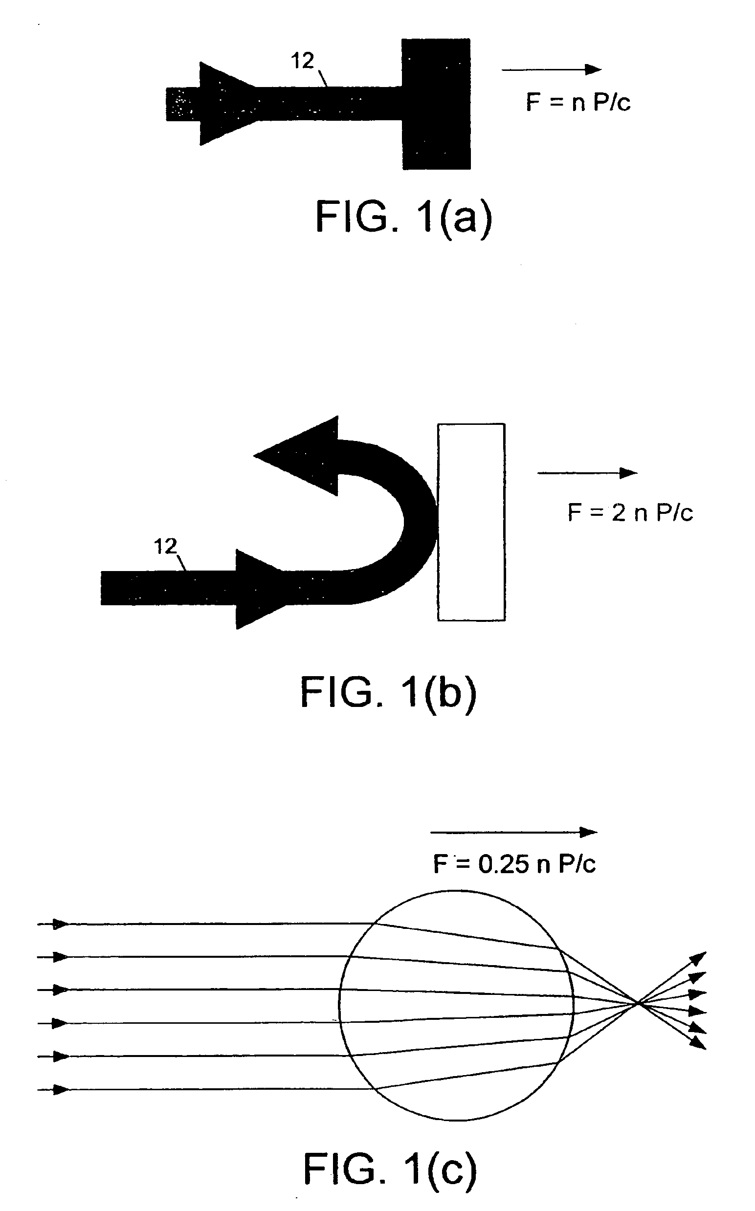
FIGS. 1(a)-1(c) illustrate the physical principles behind an optical accelerometer 10, constructed according to the present invention. In the present invention, the optical accelerometer uses radiation pressure from an optical beam in...


PUM


Abstract

An optical accelerometer for detecting an acceleration of a proof mass includes a source of optical radiation for generating a pair of beams of output radiation. The pair of beams of optical radiation exerts radiation pressure on the proof mass, so as to maintain the proof mass in an equilibrium position along a sensing axis. A position detecting system detects a displacement from the equilibrium position of the proof mass along the sensing axis in response to an inertial force acting on the proof mass. A modulator adjusts the intensity of each one of the pair of beams, so as to restore the proof mass to the equilibrium position along the sensing axis. The difference in the adjusted intensities of each one of the pair of beams is representative of the acceleration, resulting from the inertial force, of the proof mass along the sensing axis.

Description

STATEMENT REGARDING FEDERALLY SPONSORED RESEARCHNot ApplicableREFERENCE TO MICROFICHE APPENDIXNot ApplicableFIELD OF THE INVENTIONThe present invention relates generally to accelerometers, and more particularly to optically rebalanced accelerometers.BACKGROUND OF THE INVENTIONInstruments which can sense departures of their own reference frame from an inertial reference frame are of practical and commercial use in many areas, for example inertial navigation and guidance. Such departures include accelerations, by way of example. Acceleration is commonly sensed by measuring either the displacement of a proof mass in response to an inertial force, or the restoring force necessary to restore the displacement of a proof mass.Accelerometers that use electromechanical components are known in the art. In particular, multi-axis sensors are useful for inertial sensing of motion in three dimensions. In the past, such sensors have been constructed from relatively large and expensive electromagne...

Claims


Application Information

Patent Timeline
Patent Type & Authority Patents(United States)
IPC IPC(8): G01P15/08G01P15/13G01P15/093G21K1/00
CPCG01P15/08G01P15/13G01P15/093
Inventor KELLEHER, WILLIAM P.SMITH, STEPHEN P.STONER, RICHARD E.
Owner CHARLES STARK DRAPER LABORATORY
Why Eureka
Try Eureka