

Brushless DC motor
a brushless dc motor and motor technology, applied in the direction of dynamo-electric machines, magnetic circuit rotating parts, magnetic circuit shapes/forms/construction, etc., can solve the problems of harmonic vibration or noise, poor energy efficiency, and deterioration of motor characteristics,
- Summary
- Abstract
- Description
- Claims
- Application Information
AI Technical Summary
Benefits of technology
Problems solved by technology
Method used
Image

Examples
first embodiment
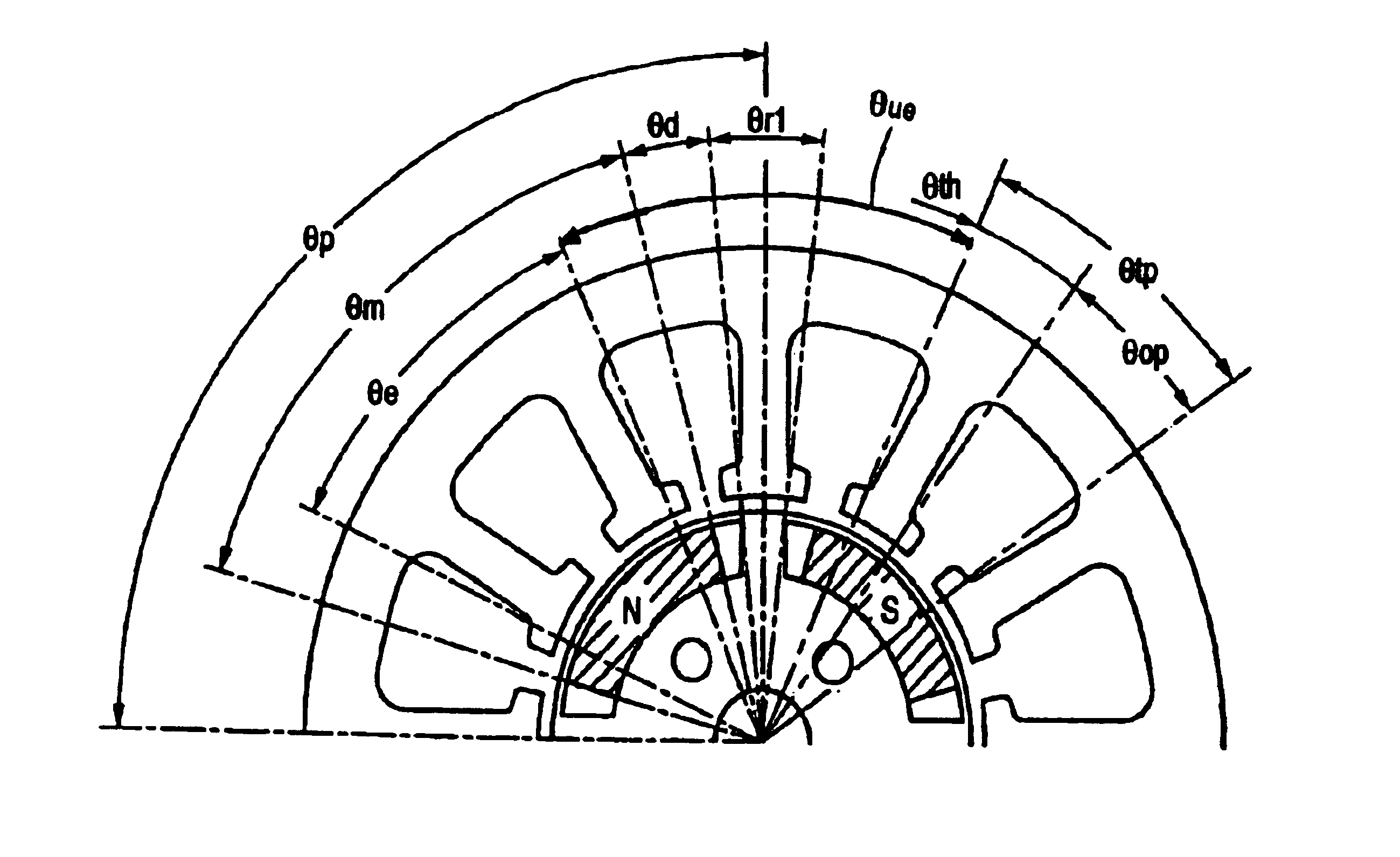
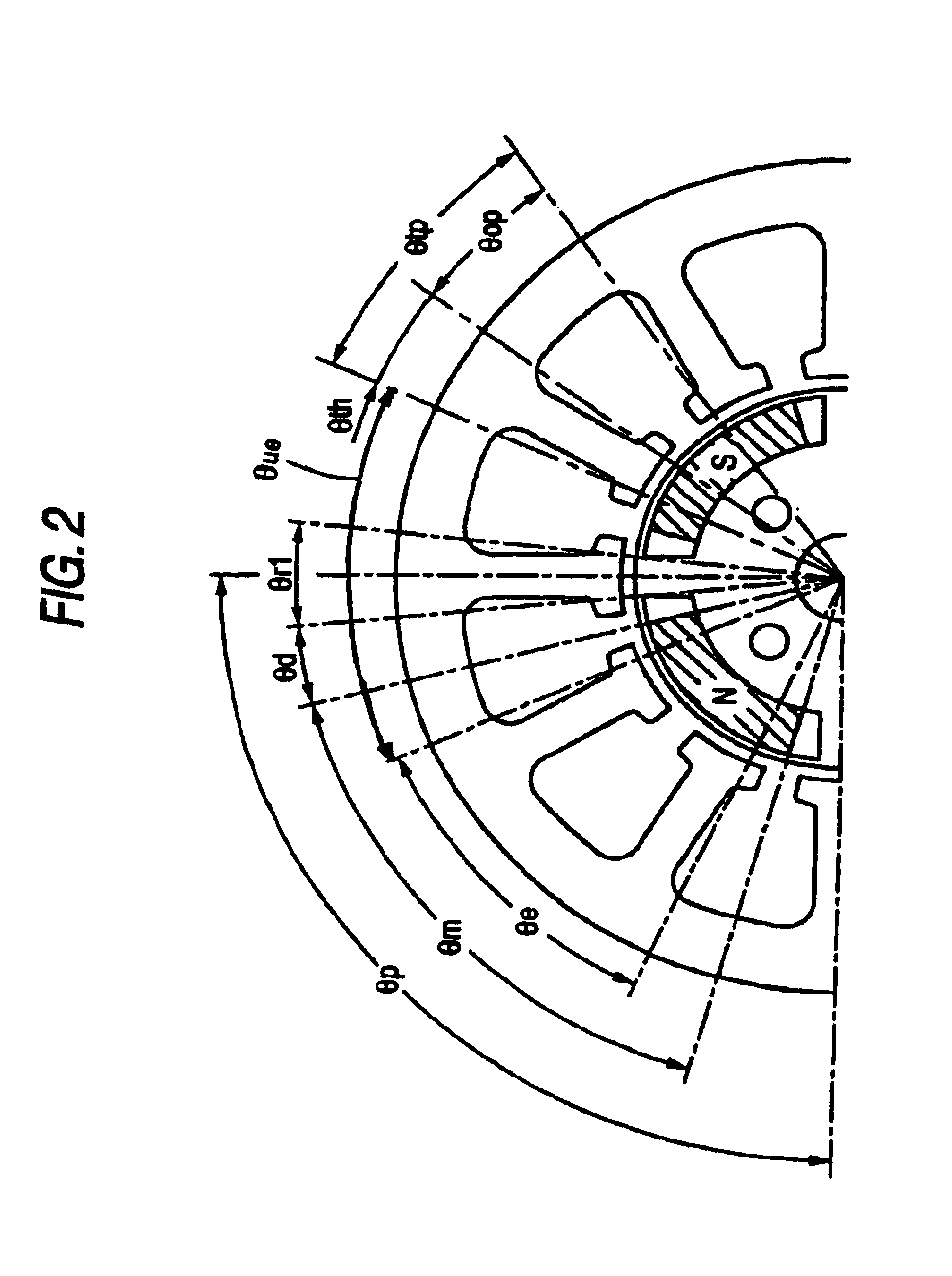
A detailed explanation will be given of embodiments embodying the invention in reference to the attached drawings as follows. The embodiment embodies the invention as a brushless DC motor constituted by a stator having 12 slots and a rotor having 4 poles. According to the embodiment, an angular range of an opening angle used in each of portions of the stator and the rotor, is defined by a portion facing an air gap (inner periphery in the stator, outer periphery in the rotor).
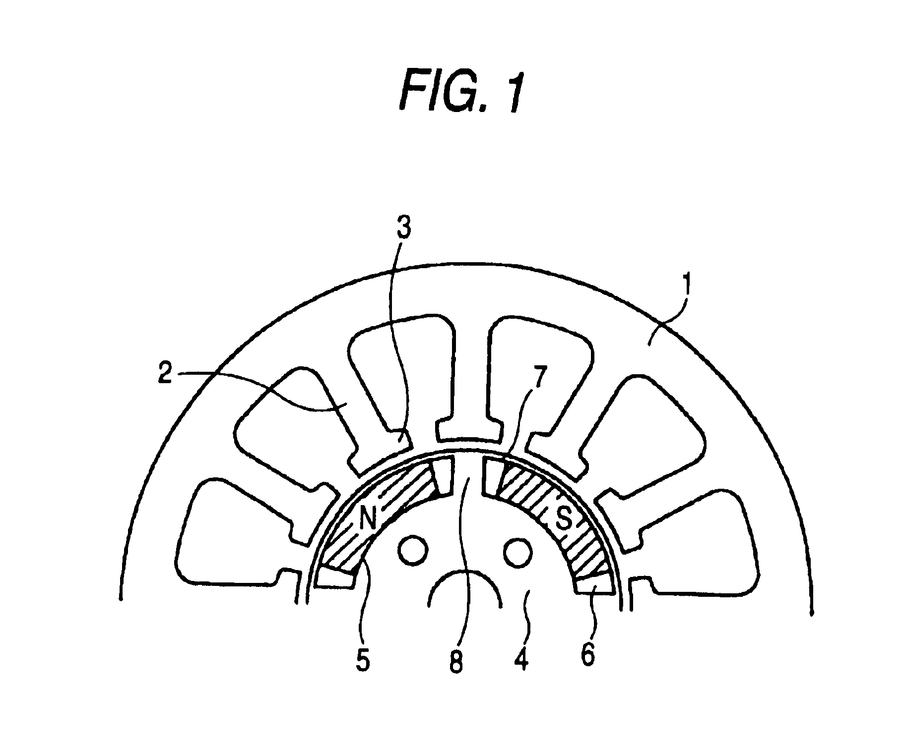
A brushless DC motor according to the embodiment is constituted by a structure as shown in FIG. 1. A stator 1 of the brushless DC motor is provided with 12 pieces of teeth 2. A front end of the respective tooth 2 is formed with a tip 3. Meanwhile, a rotor 4 is provided with 4 pieces of permanent magnets 5. The respective permanent magnet 5 is formed by a shape of a so-to-speak substantially circular arc along an outer periphery of the rotor 4. A respective magnet attaching hole 6 in the rotor 4 is formed to be l...
second embodiment
A detailed explanation will be given of embodiments embodying a brushless DC motor according to the invention in reference to the attached drawings as follows. According to the embodiment, the invention is embodied as a brushless DC motor constituted by a stator of 12 slots and a rotor of 4 poles.
A brushless DC motor according to the embodiment is constituted by a structure as shown by FIG. 16. A stator 52 of the brushless DC motor includes 12 pieces of teeth 51 aligned at equal pitches in a circumferential direction. Meanwhile, a rotor 54 includes 4 pieces of magnets 53. The respective magnet 53 is formed by a shape of a so-to-speak substantially circular arc along an outer periphery of the rotor 54. A respective magnet attaching hole 55 at the rotor 54 is formed to be longer than the magnet 53 in the circumferential direction. The respective magnet 53 is attached to the center of the respective magnet attaching hole 55 in the circumferential direction. Therefore, there are gaps at...
third embodiment
A detailed explanation will be given of embodiments embodying the invention in reference to the attached drawings as follows.
A brushless DC motor according to the embodiment is constituted as shown by FIG. 28. FIG. 28 is shown by omitting a lower half of the motor. A rotor 80 of FIG. 28 is provided with 4 pieces of magnets 81 and a pole pair number is 2. Therefore, an electric angle with regard to the rotor 80 is twice as much as a geometrical angle. The rotor 80 is formed with 4 of magnet attaching holes 82. The respective is attached with a single one of the magnet 81. There is present a magnetic member region 83 also on an outer side of the respective magnet 81 in the rotor 80. Further, there is present a bridge 84 connecting an outer side and an inner side of the magnet 81 by a magnetic member between the contiguous magnets 81. A stator 90 of FIG. 28 includes 12 pieces of teeth 91. Although windings are provided actually to the respective teeth 91, the windings are omitted in FI...
PUM
 Abstract
Description
Claims
Application Information