Non-contact position sensor having specific configuration of stators and magnets

Inactive Publication Date: 2005-03-15
MIKUNI CORP
View PDF12 Cites 21 Cited by
  • Summary
  • Abstract
  • Description
  • Claims
  • Application Information

AI Technical Summary

Benefits of technology

Accordingly, it is the object of the present invention to provide a non-contact posit

Problems solved by technology

However, only approximately 150° of the output characteristic angle is usable, with resolution falling accordingly when less than 150° is

Method used


Image

  • Non-contact position sensor having specific configuration of stators and magnets
  • Non-contact position sensor having specific configuration of stators and magnets
  • Non-contact position sensor having specific configuration of stators and magnets

Examples


Embodiment Construction

Reference will now be made in detail to a present preferred embodiment of the present invention, examples of which are illustrated in the accompanying drawings, wherein like reference numerals refer to elements throughout.

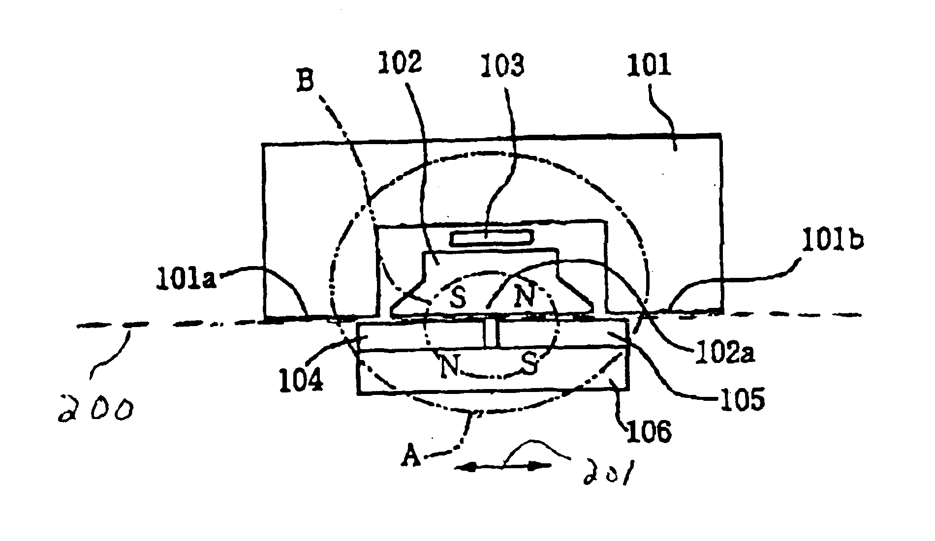
FIGS. 3(A), 3(B) and 3(C) are views showing a configuration for a linear sensor as a non-contact position sensor, according to an embodiment of the present invention. The sensor includes a first stator 101, a second stator 102, a hall element 103 located between the first stator 101 and the second stator 102, moveable magnets 104 and 105 located facing the first stator 101 and the second stator 102, and a slider 106 joining the moveable magnets. The first stator 101 is reverse-C-shaped and has magnet facing sides 101a and 101b on both sides, the second stator 102 has just one magnet facing side 102a, and these three magnet facing sides 101a, 101b and 102a are arranged along a straight line locus 200. In this embodiment, locus 200 is a straight line. However, the pr...


PUM


Abstract

A non-contact position sensor including a first stator having two magnet facing sides, a second stator having one magnet facing side aligned with the two magnet facing sides along a locus, a hall element between the first and second stators, and two magnets located next to each other along the locus opposite the three magnet facing sides so as to move freely along the locus. When configured as a rotary sensor, an arbitrary angle of usage can be set. When configured as a linear sensor, a magnet can be made thick without increasing leakage of magnetic flux.

Description

BACKGROUND OF THE INVENTION1. Field of the InventionThe present invention relates to a non-contact position sensor for sensing changes in magnetic flux and converting the changes to a voltage, and in particular relates to a sensor employing a stator with three magnet facing sides that face magnets.2. Description of the Related ArtRotary sensors and linear sensors are examples of non-contact position sensors employing a hall element. FIG. 1 is a cross-sectional view of the center of a rotary sensor disclosed in Japanese Laid-open Publication No. Hei. 8-35809. As shown in FIG. 1, a coupling shaft 1 has a cylindrical rotor 2 on an outer side, with a cylindrical permanent magnet 3 being fixed to the inner side of the rotor 2. Two semi-cylindrical stators 4 and 5 are then fixed at the inner side of the permanent magnet 3 in such a manner as to leave a slight gap with respect to the permanent magnet 3. A gap 6 extending diameter-wise is formed between the stators 4 and 5 and a hall elemen...

Claims


Application Information

Patent Timeline
IPC IPC(8): G01D5/14G01D5/12G01B7/30G01B7/00G01D5/245
CPCG01D5/145
Inventor MURAJI, TETSUOSEKIYA, MITSURU
Owner MIKUNI CORP
Why Eureka
Try Eureka