

Scanning of biological samples
- Summary
- Abstract
- Description
- Claims
- Application Information
AI Technical Summary
Benefits of technology
Problems solved by technology
Method used
Image

Examples
Embodiment Construction
m according to the present invention;
[0037]FIG. 13 shows one illustrative exemplary and more detailed configuration of the image detection apparatus of the system generally shown in FIG. 12;
[0038]FIG. 14 shows another alternate illustrative exemplary and more detailed configuration of the image detection apparatus of the system generally shown in FIG. 12;
[0039]FIG. 15A illustrates another alternative embodiment of an image detection apparatus in side part-section view;
[0040]FIG. 15B illustrates the embodiment of FIG. 15A in top view;
[0041]FIG. 16 shows a top view of the transport mechanism of the apparatus of FIG. 15A;
[0042]FIGS. 17A and 17B show, respectively, a top and a side exterior view of an image detecting apparatus having an added multi-sample mechanism;
[0043]FIGS. 18A-18C show another embodiment of an image detection apparatus;
[0044]FIG. 19 shows schematically an optical arrangement that may be used with the apparatuses of FIGS. 15-18;
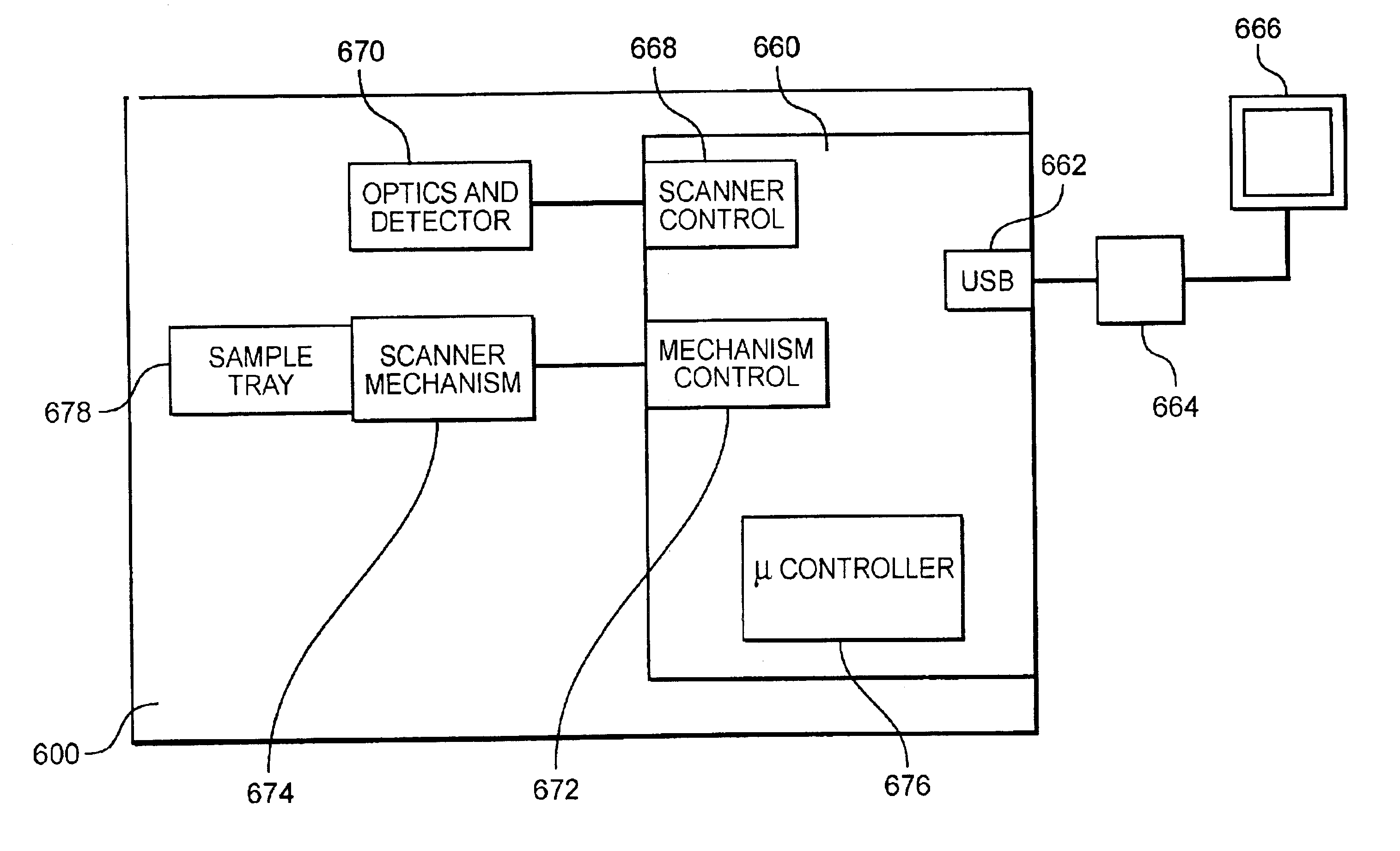
[0045]FIG. 20 is a block diagram showin...
PUM
 Abstract
Description
Claims
Application Information