
Methods and apparatuses for providing synchronization in a communication network

a communication network and communication network technology, applied in the direction of time division multiplexing selection, transmission, synchronous/start-stop systems, etc., can solve the problems of network synchronization consequently stopping, communication may stop functioning, and the schedule has a drawback

Inactive Publication Date: 2005-03-15
NET INSIGHT INTPROP
View PDF6 Cites 57 Cited by
  • Summary
  • Abstract
  • Description
  • Claims
  • Application Information

AI Technical Summary

Benefits of technology

"The invention provides a way for a node to monitor and coordinate the reception of a frame synchronization signal on a bitstream. If the frame synchronization signal is not received as expected, the node will take over and provide its own frame synchronization signal based on a locally generated clock signal. This allows for maintaining frame synchronization in the event of a failure in the network. The invention also allows for re-synchronizing links or link sections that do not receive a frame synchronization signal with the network frame rate when the original signal is recovered. The invention is particularly useful in DTM networks, where frame synchronization is provided in a tree-like, top-down manner and each node has access to at least one control slot and a number of data slots within each frame."

Problems solved by technology

However, this scheme has a drawback when being implemented in a large network.
When a link or node failure occurs that breaks the distribution tree, the links (and all the nodes having access thereto) at the leaf of the tree from the failure point do no longer receive the propagated frame synchronization signal, and network synchronization consequently stops is deteriorated in this leaf.
However, before the new path is established, the communication may stop functioning, which of course is a mayor disadvantage.

Method used


Image

  • Methods and apparatuses for providing synchronization in a communication network
  • Methods and apparatuses for providing synchronization in a communication network
  • Methods and apparatuses for providing synchronization in a communication network

Examples


Embodiment Construction

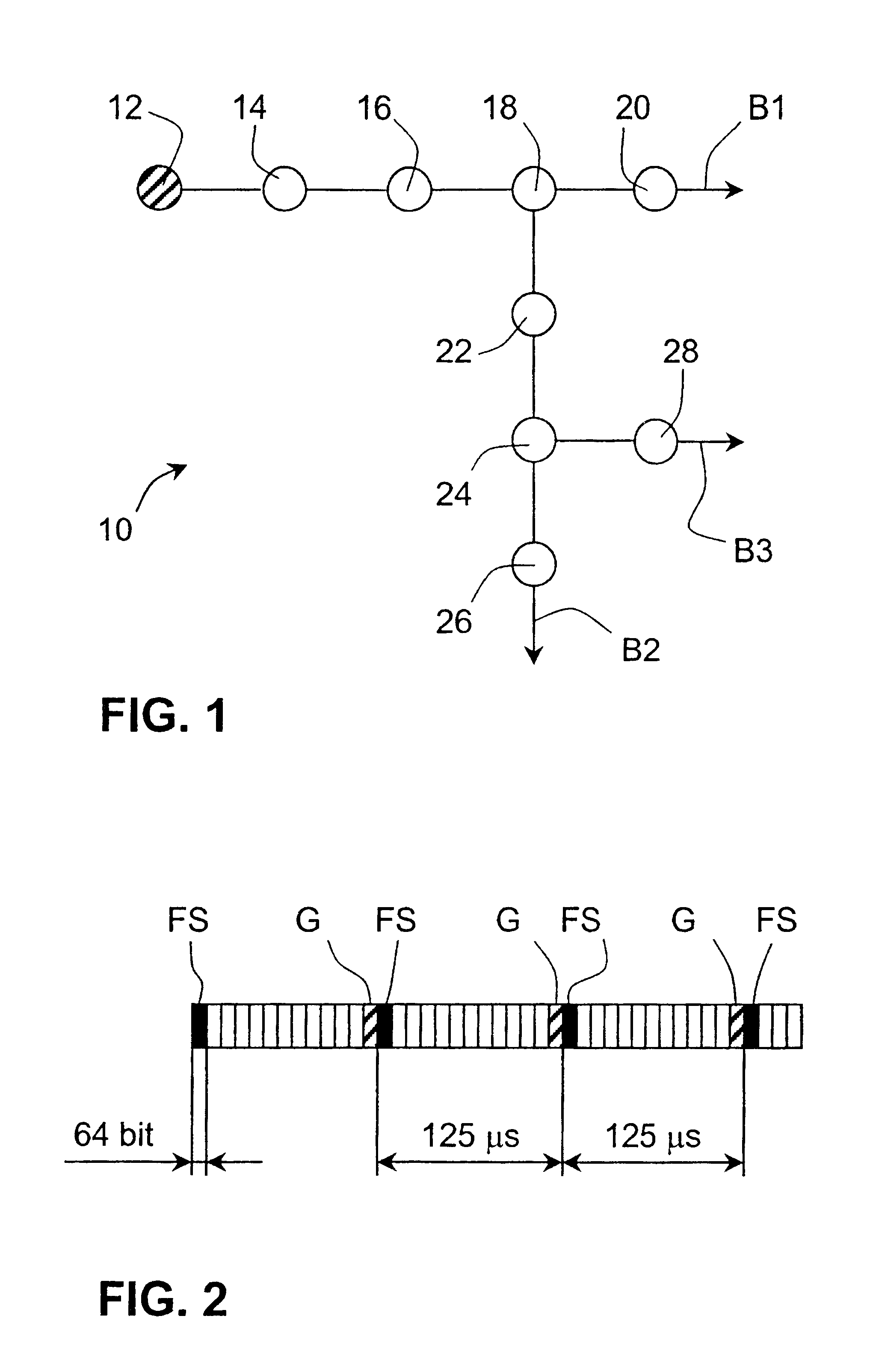
A network 10 operating according to an embodiment of the invention will now be describe with reference to FIG. 1. The network section shown in FIG. 1 includes three bitstreams B1, B2, and B3 propagating in the directions indicated by arrows in the figure and transferring data between nodes 12-28 of the network. An example of the structure of each one of the bitstreams in FIG. 1 will be described below with reference to FIG. 2. In the network section of FIG. 1, nodes 12, 14, 16, 18, and 20 are connected to bitstream B1, nodes 18, 22, 24, and 26 are connected to bitstream B2, and nodes 24 and 28 are connected to bitstream B3. Each node typically provides end users connected to the respective node with access to the network bitstreams. In order to communicate with other nodes, a node will transmit data into, or read data from, allocated time slots of the bitstream concerned. If a node on a first bitstream, for example node 14 on bitstream B1, wishes to transmit data to a node on anothe...


PUM


Abstract

The present invention refers to methods and apparatuses for providing synchronization in a time division multiplexed network, wherein data is transferred on multi-access bitstreams in circuit-switched channels that are defined by respective time slots of regularly recurrent frames of said bitstreams, said frames being defined by regularly recurrent frame synchronization signals transferred on said bitstreams. According to the invention an auxiliary regularly recurrent frame synchronization signal is generated and selected as a basis for defining said frames on a bitstream if the frame synchronization signal that is used as a basis for synchronizing said frames during normal operation is not detected in accordance with an expected frame rate.

Description

FIELD OF INVENTIONThe present invention refers to methods and apparatuses for providing synchronization in a time division multiplexed communication network, more specifically in networks wherein data are transferred in bitstreams that are divided into regularly recurrent frames of time slots.Background and Prior ArtToday, new types of circuit-switched communication networks are being developed for the transfer of information using time division multiplexed, multi-access bitstreams, wherein each bitstream is divided into regularly recurrent frames, or cycles, each frame in turn being divided into time slots.An example of such a new network technology is the DTM (Dynamic Synchronous Transfer Mode) network, which for example is described in “The DTM Gigabit Network”, Christer Bohm, Per Lindgren, Lars Ramfelt, and Peter Sjödin, Journal of High Speed Networks, 3(2):109-126, 1994, and in “Multi-gigabit networking based on DTM”, Lars Gauffin, Lars H{dot over (a)}kansson, and Björn Pehrson...

Claims


Application Information

Patent Timeline
Patent Type & Authority Patents(United States)
IPC IPC(8): H04L12/43H04L12/427
CPCH04L12/43H04L12/52H04L7/044H04L7/08H04Q11/04
Inventor BOHM, CHRISTERDANIELSON, MAGNUSLINDGREN, PER
Owner NET INSIGHT INTPROP
Learn More