Intelligent hydraulic manifold used in an injection molding machine

a hydraulic manifold and intelligent technology, applied in the direction of static/dynamic balance measurement, servomotors, programme control, etc., can solve the problem that failure of any manifold-mounted microcontroller will only require its replacemen

Inactive Publication Date: 2005-03-15
HUSKY INJECTION MOLDING SYST LTD
View PDF27 Cites 27 Cited by
  • Summary
  • Abstract
  • Description
  • Claims
  • Application Information

AI Technical Summary

Benefits of technology

An object of the present invention is to overcome the problems noted above by providing a local processor disposed near the actuator so that control functions are moved closer to the actuator and away from the central processor. Preferably, a microcontroller is mounted directly on each hydraulic fluid distribution manifold, and this microcontroller controls the actuators coupled to that manifold. Each hydraulic actuator can be controlled from a local processor, eliminating the need for a great number of wires between the actuator and the analog signal processor and / or the machine controller, such as a programmable logic controller. This enables modular control sub-systems to be realized. Also, a failure of any manifold-mounted microcontroller will only require its replacement, not the replacement of the central controller or the other manifold microcontrollers.

Problems solved by technology

Also, a failure of any manifold-mounted microcontroller will only require its replacement, not the replacement of the central controller or the other manifold microcontrollers.

Method used


Image

  • Intelligent hydraulic manifold used in an injection molding machine
  • Intelligent hydraulic manifold used in an injection molding machine
  • Intelligent hydraulic manifold used in an injection molding machine

Examples


Embodiment Construction

1. Introduction

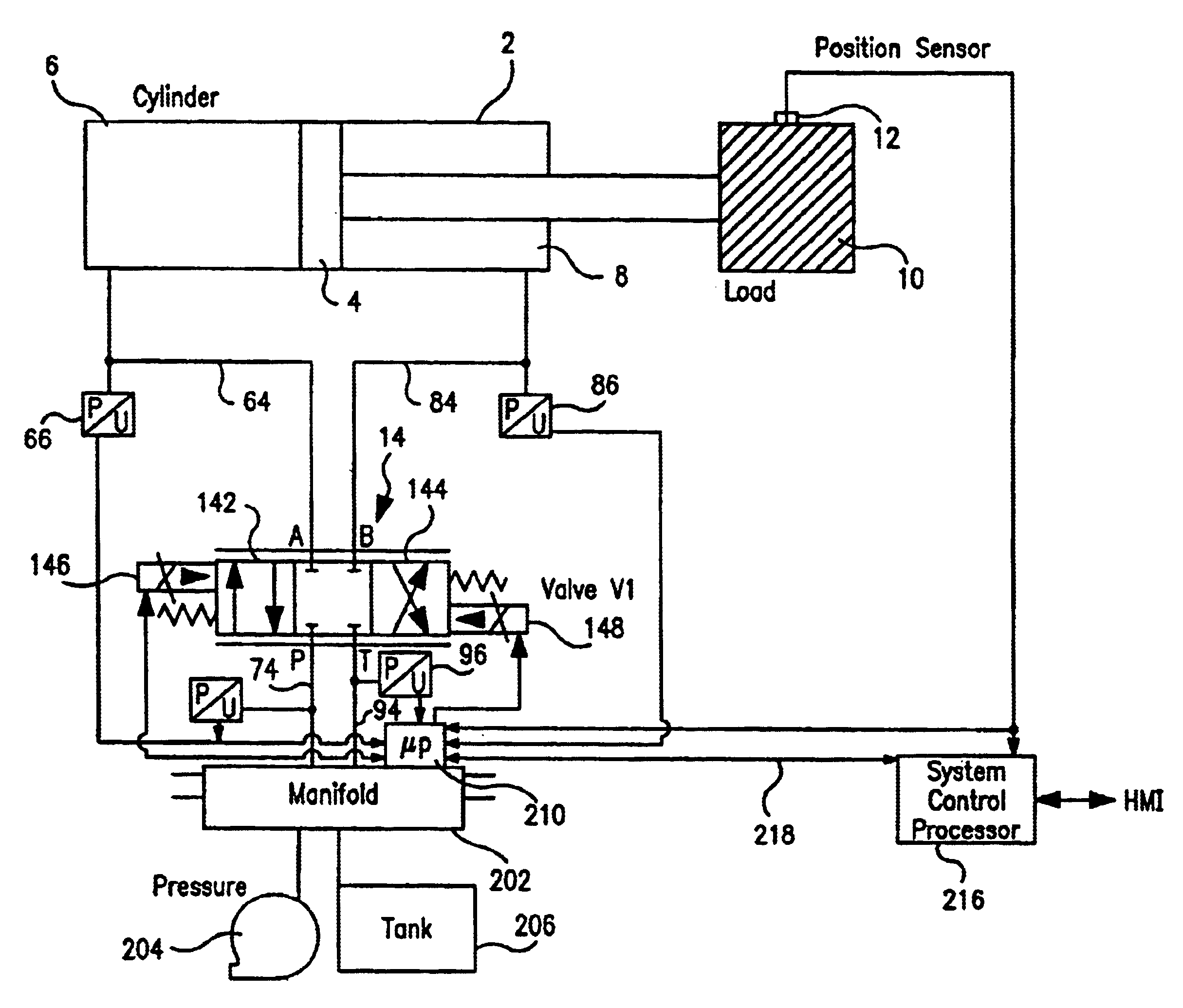
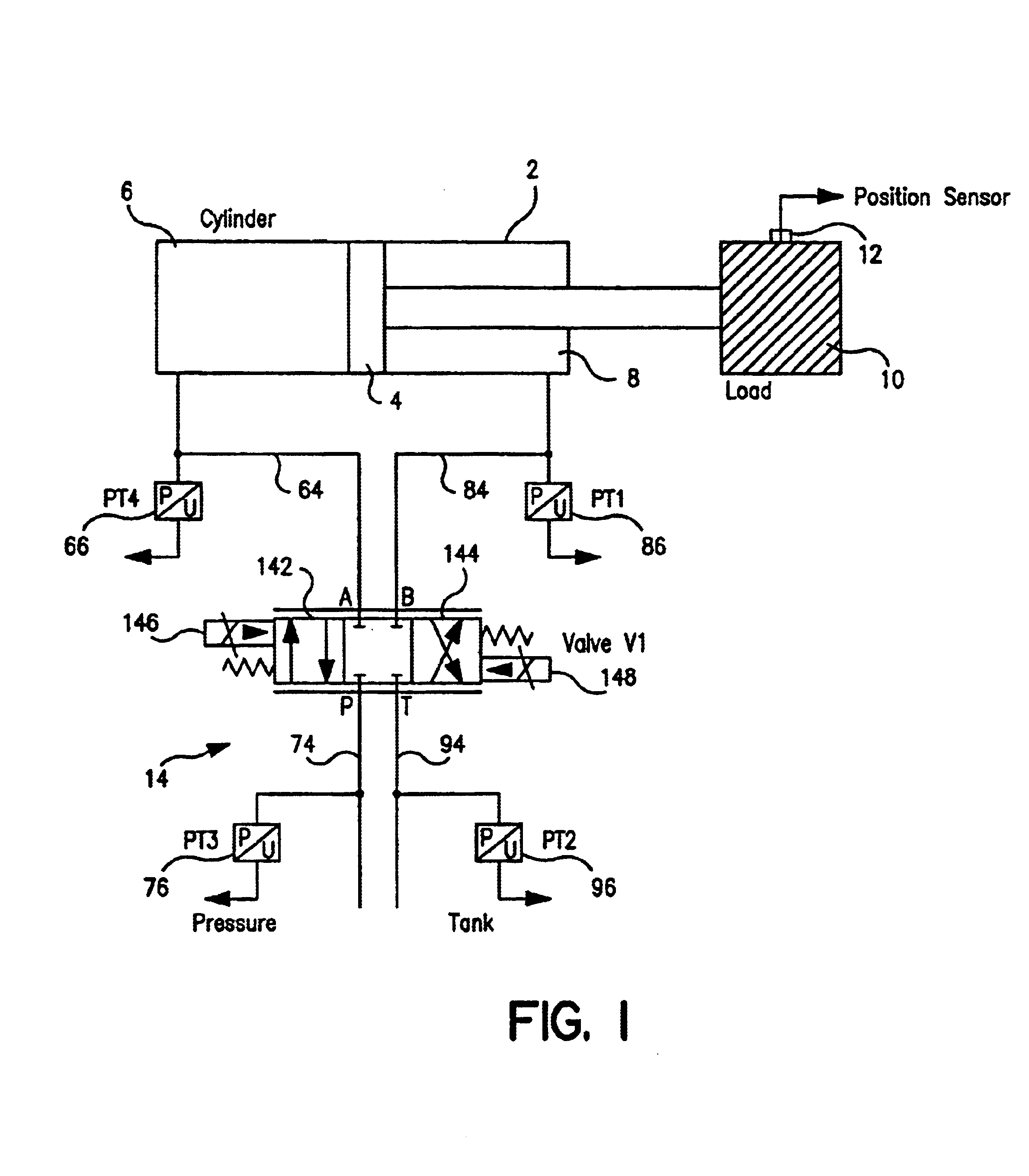
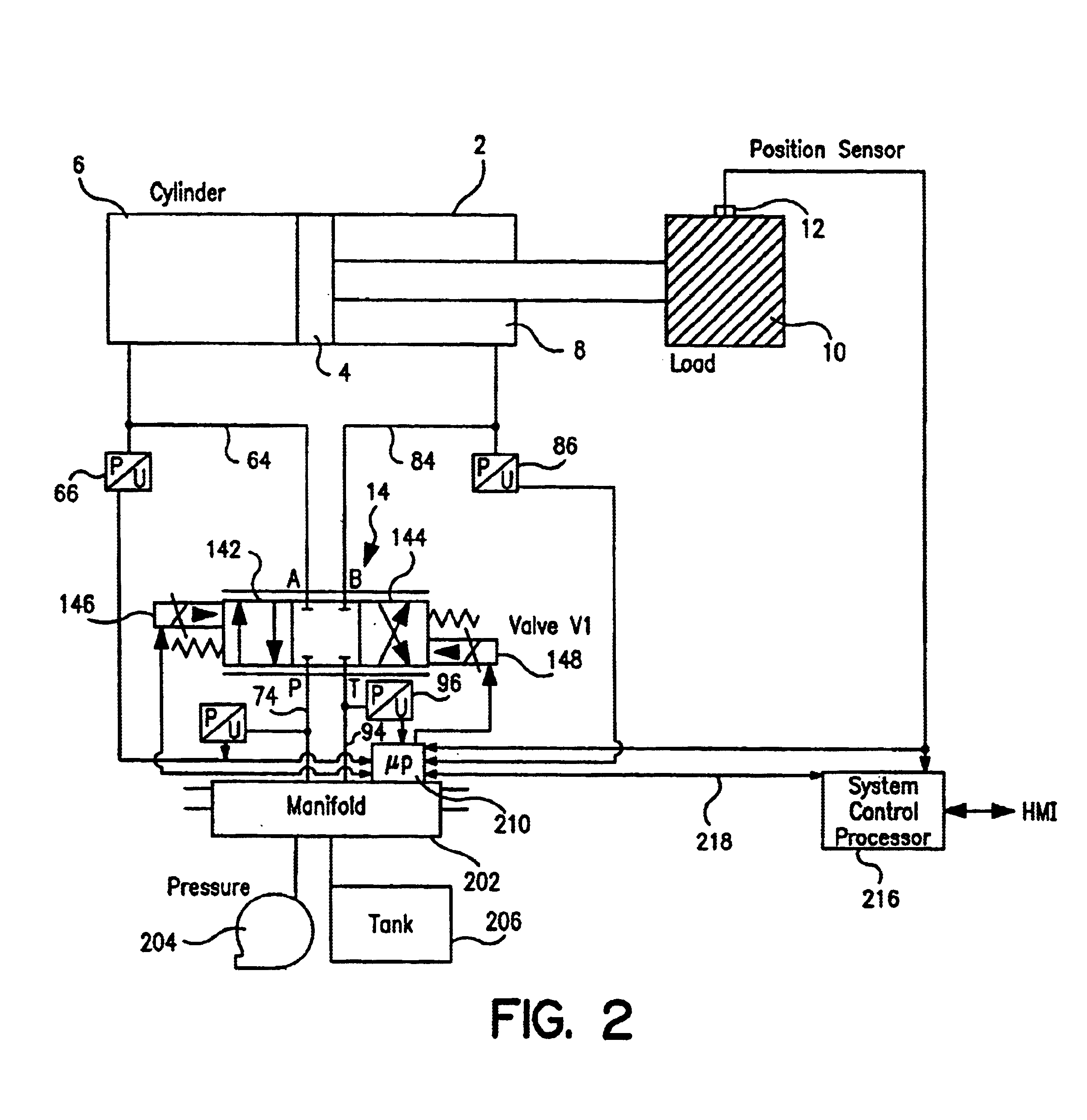
The present invention will be described with respect to controlling hydraulic actuators (both linear and rotary) in an injection molding machine. However, the invention is not limited to injection molding machines and will solve actuator control problems in a wide variety of applications. For example, the fluid described below could be any known liquid or gas useful in controlling an actuator. The scope of the present invention is to be ascertained from the appended claims and not the detailed description of the preferred embodiments.

The present invention features a computer, processor, microcontroller, or microcontroller mounted on a hydraulic fluid manifold and / or actuator to provide localized control, enhanced reliability, and reduced wiring in hydraulic actuator control systems. Mounting the processor on the manifold and / or actuator thus incorporates the processing and control functionality of a process control unit in an integrated mechanical assembly including h...


PUM

PropertyMeasurementUnit
pressureaaaaaaaaaa
pressure dropaaaaaaaaaa
flow rate linearizationaaaaaaaaaa

Abstract

Apparatus and method for controlling a hydraulic actuator in an injection molding machine, where the hydraulic actuator moves in a linear or rotary manner to effect movement of an injection molding device, such as a mold clamp. A microcontroller is locally disposed adjacent to the actuator or the hydraulic fluid distribution manifold to cause the actuator to drive the device. The microcontroller is electrically coupled to the system control processor. This distributed control architecture increases system processing throughput, enhances reliability, and permits easier upgrades / repair. Preferably, the microcontroller is mounted on the manifold and controls all of the actuators supplied from that manifold.

Description

BACKGROUND OF THE INVENTION1. Field of the InventionThe present invention relates to an apparatus and methods for controlling a hydraulic actuator for use in an injection molding machine, and more particularly to controlling such a hydraulic actuator (both linear and rotary) with a processor which is disposed locally near the actuator and / or the hydraulic manifold.2. Related ArtInjection molding machines produce great quantities of products at high speed. For example, the widely-used PET plastic drink containers are made at production rates of thousands per hour. During these high speed operations, various injection molding machine devices (such as the molding clamp assembly, the injectors, various control switches, and other machine components) are moved using a number of hydraulic actuators. Such hydraulic actuators are supplied with pressurized hydraulic fluid that causes movement of an internal diaphragm or piston which, in turn, drives the molding device. A control valve contro...

Claims


Application Information

Patent Timeline
Patent Type & Authority Patents(United States)
IPC IPC(8): B23K3/06B29C45/82F15B9/09F15B11/028
CPCB23K3/0623B29C45/82G05B2219/41309B29C2945/76006B29C2945/76083B29C2945/76498B29C2945/76505B29C2945/76531B29C2945/76545B29C2945/76568B29C2945/76595B29C2945/76759B29C2945/76785B29C2945/76936B29C2945/76939B29C2945/76966G05B2219/41124
Inventor CHOI, CHRISTOPHERCROOKSTON, IAN
Owner HUSKY INJECTION MOLDING SYST LTD
Why Eureka
Try Eureka