Elevator rope arrangement

a technology of a vertical rope and a sleeve is applied in the field of vertical rope arrangement, which can solve the problems effective transmission of frictional heat from the rope, and achieve the effects of low volume-to-area ratio, reduced internal shear force in the rope, and small diameter

Inactive Publication Date: 2005-03-22
KONE CORP
View PDF41 Cites 7 Cited by
  • Summary
  • Abstract
  • Description
  • Claims
  • Application Information

AI Technical Summary

Benefits of technology

The object of the present invention is to eliminate the drawbacks of prior art and achieve a new type of elevator rope arrangement, in which the elevator ropes are divided into two categories: a) suspension ropes, whose function is to connect the elevator car and the counterweight to each other and to support them, and b) a new type of hoisting rope made of synthetic material, whose function is to receive the unbalance between the counterweight on the one hand and the elevator car and its load on the other hand and to move the elevator car.
The thin and flat hoisting rope allows the use of a traction sheave that is considerably smaller in diameter and lighter than those used at present. Therefore, also the moment required for moving the elevator car is low, and consequently it is possible to use a small and cheap hoisting motor. The flat band-like shape of the rope distributes the pressure imposed by the rope on the traction sheave or diverting pulley more uniformly on the surface of the traction sheave. Further, sliding of the fibers relative to each other is minimized, and so the internal shear forces in the rope are also minimized. In addition, the ratio of volume to area is low which means that frictional heat is effectively transmitted from the rope to the environment. Furthermore, the sheath of the hoisting rope can easily be coated with various materials, so the friction and abrasion characteristics can be optimized for different traction sheave materials. The small motor and small traction sheave are well applicable to an elevator without machine room because the hoisting motor with the traction sheave can be easily accommodated in the elevator shaft.

Problems solved by technology

In addition, the ratio of volume to area is low which means that frictional heat is effectively transmitted from the rope to the environment.

Method used


Image

  • Elevator rope arrangement
  • Elevator rope arrangement
  • Elevator rope arrangement

Examples


Embodiment Construction

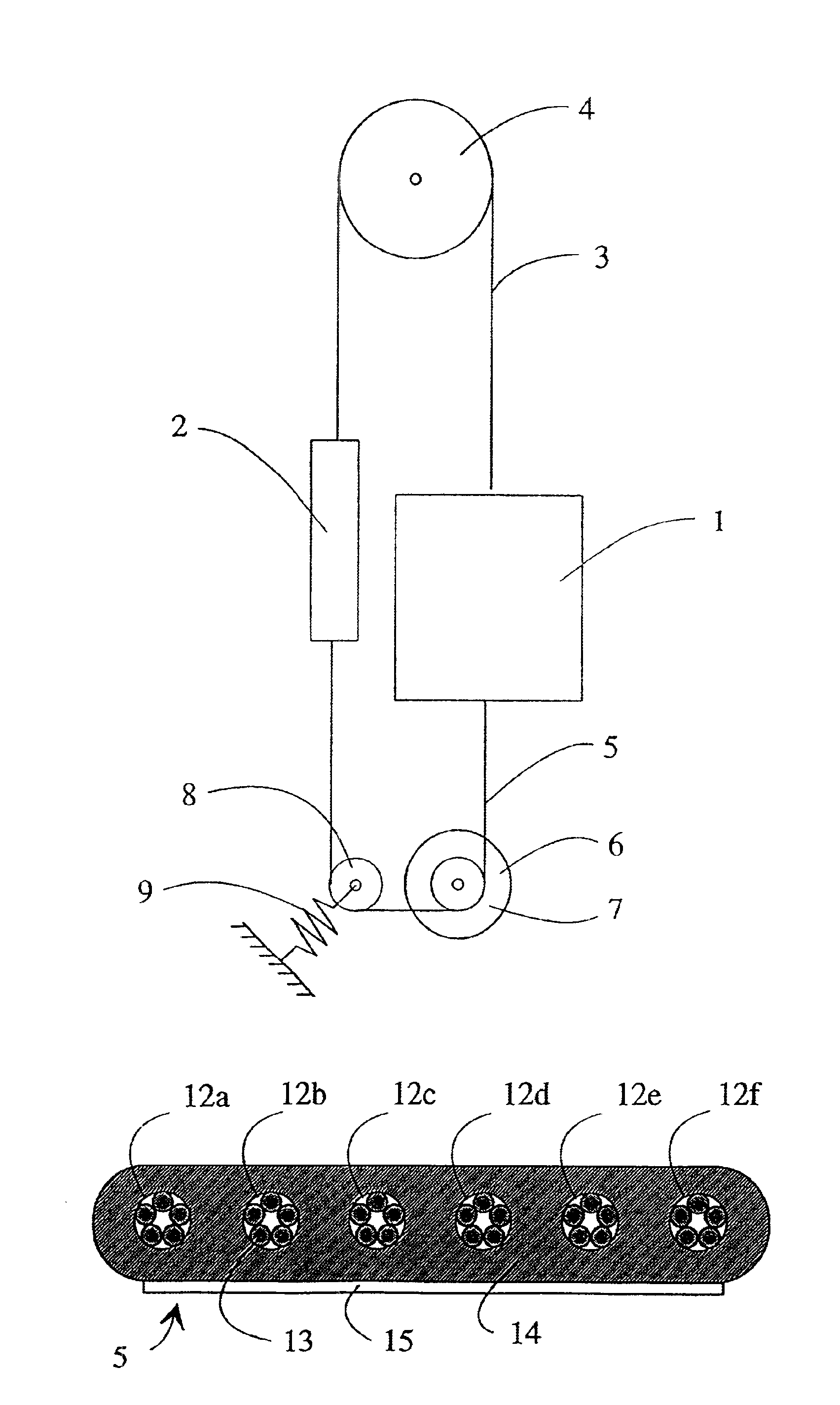
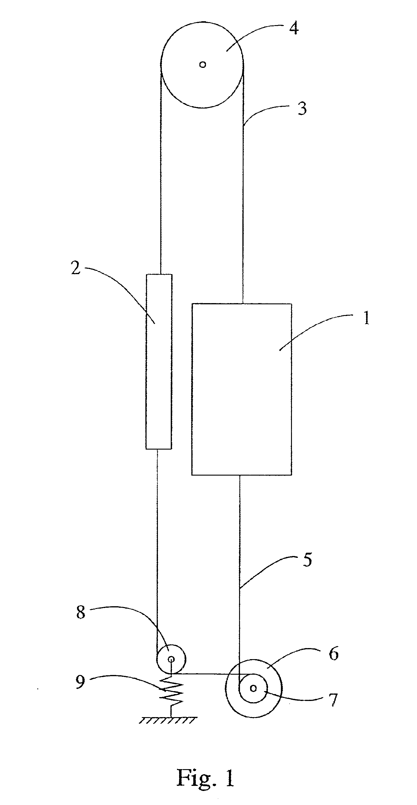
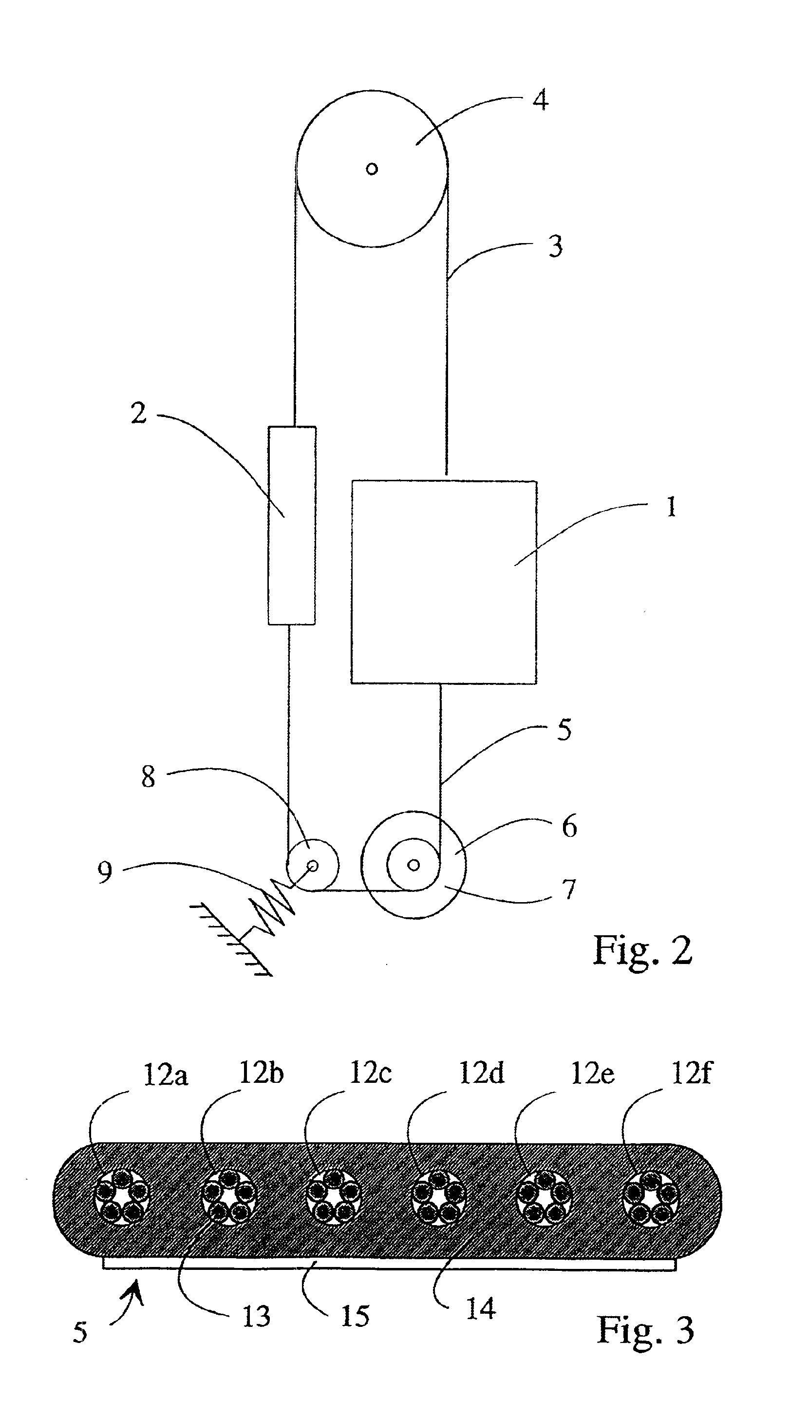
FIG. 1 shows a traction sheave elevator according to the invention, comprising an elevator car 1 and a counterweight 2 travelling along guide rails in an elevator shaft and suspended on suspension ropes 3. The steel suspension ropes 3 are fixed to the top part of the elevator car 1 and passed via a diverting pulley 4 in the elevator shaft to the counterweight 2. The substantially round hoisting ropes 5 used to move the elevator car and counterweight, made of synthetic material, are flexible and substantially thin as compared with the suspension ropes. The hoisting ropes are attached by their first end to the lower part of the elevator car 1, from where the ropes are passed to the lower part of the counter-weight 2 via the traction sheave 7 of a drive machine 6 placed on the bottom of the elevator shaft below the elevator car 1 and via a diverting pulley 8 placed on the bottom of the elevator shaft below the counter-weight. The drive machine is e.g. a discoid electric motor of a flat...


PUM

PropertyMeasurementUnit
angle of contactaaaaaaaaaa
tensile strengthaaaaaaaaaa
widthaaaaaaaaaa

Abstract

Elevator rope arrangement in which the elevator car and counterweight, travelling along guide rails in an elevator shaft, are supported by suspension ropes, which are attached to the top part of the elevator car and passed via at least one diverting pulley to the counterweight. Separate hoisting ropes are attached to the lower part of the elevator car and passed to lower part of the counterweight via at least one diverting pulley. The hoisting rope is a substantially thin rope made of synthetic fiber and having a sheath made of plastic material.

Description

FIELD OF THE INVENTIONThe present invention relates to an elevator rope arrangement.DESCRIPTION OF THE BACKGROUND ARTIn traction sheave elevators, the elevator car and counterweight are suspended on round steel ropes. Normally, the same ropes act both as suspension ropes, whose function is to support the elevator car and counterweight, and as hoisting ropes serving to move the elevator car and counterweight. Therefore, the ropes must be designed to carry the entire load, even if, when a counterweight is used, the force needed to move the elevator is very small—in an extreme case nearly zero when the counterweight and the elevator car with the car load are equal in weight.In prior art, there are also solutions having separate suspension ropes and hoisting ropes. Such an elevator is presented e.g. in U.S. Pat. No. 5,398,781. In the elevator described in this specification, the suspension rope is attached to the top part of the elevator car and passed via diverting pulleys to a lever e...

Claims


Application Information

Patent Timeline
Patent Type & Authority Patents(United States)
IPC IPC(8): B66B11/08B66B11/00B66B11/04D07B1/22D07B1/00D07B1/16B66B7/00B66B7/06
CPCB66B11/008B66B11/08D07B2501/2007D07B2201/2087D07B1/22D07B5/006
Inventor AULANKO, ESKOMAKIMATTILA, SIMO
Owner KONE CORP
Why Eureka
Try Eureka