Constant seating stress gasket system

a gasket system and constant seating technology, applied in the direction of couplings, cable terminations, mechanical devices, etc., can solve the problems of gasket degradation, leakage and associated seal failure, damage to sealing components, etc., to reduce the need for calibrated assembly tools, reduce the need for calibration assembly tools, and reduce the effect of material relaxation

Inactive Publication Date: 2005-03-22
JJENCO
View PDF11 Cites 62 Cited by
  • Summary
  • Abstract
  • Description
  • Claims
  • Application Information

AI Technical Summary

Benefits of technology

These and other needs are met in the present invention, which includes a gasket in which the gasket seating stress is effectively controlled, the gasket seating stress is evenly distributed over the entire gasket sealing area, and in-service creep relaxation of the material is limited, and in which the sealing capability of the gasket is not primarily defined by the type and configuration of the sealing material, but by the configuration of the carrier ring. Generally, the present invention includes a carrier ring over which a sealing material suitable to environmental and process conditions has been affixed in the sealing region of the gasket. Various facets of the invention provide visual markers for achievement of the correct gasket compression (thereby eliminating or reducing the need for calibrated assembly tools), limit the compression of the sealing material to the desired compression, fully capture the sealing material in a confined space, and account for flange rotation in the achievement of the gasket seating stress.

Problems solved by technology

The principal problem encountered in designing and operating effective gasketed connections is seal failure and the leakage associated therewith.
Leakage from gasketed joints can be attributed to one or more of five root causes, including (a) sealing surfaces that do not meet the minimum physical conditions necessary to effect a seal, (b) insufficient gasket seating stress to effect a seal, (c) excessive gasket seating stress which results in damage to the sealing components, (d) a reduction in gasket stress due to flange rotation or in-service creep relaxation of the gasket sealing material, and (e) incompatibility of the gasket sealing material with the sealed fluid or the operating environment (which leads, over time, to gasket degradation).
With sheet gaskets, which include gaskets made of rubber, compressed fiber, polytetrafluoroethylene (PTFE), graphite, and equivalents, the performance is limited, variously, by the primary sealing material's compression characteristics, the gasket's tendency to creep in service, the gasket's ability to withstand various combinations of temperature and pressure, and degradation of the gasketing material.
However, research and field experience have shown that most spiral-wound gaskets continue to be subject to creep relaxation and inward buckling of the metal windings, both of which potentially result in leakage.
A further problem associated with the use of spiral-wound gaskets involves standards within the manufacturing process; current manufacturing processes create variability, from gasket to gasket, in the density of the filler material—in some cases, a factor of as much as 3 in difference between similar gaskets.
Thus, the repeatable achievement of a target gasket seating stress using spiral-wound gaskets is problematic.
Still another problem associated with the use of conventional gaskets is the need for calibrated assembly tools to ensure that the proper compression is achieved.
Finally, existing gaskets are subject to variable seating stresses over their surface area due to the effect of flange rotation, which may be most pronounced in raised-face flanges.
This results in non-uniform gasket seating stresses over the sealing area, since the gasket seating stress increases radially from inside to outside due to the flange rotation.

Method used


Image

  • Constant seating stress gasket system
  • Constant seating stress gasket system
  • Constant seating stress gasket system

Examples


Embodiment Construction

Three aspects of gasket seating stress control the effectiveness of the seal. First, the correct target seating stress must be determined; practically, the target gasket seating stress must exceed the stress necessary to seal the maximum temperature and pressure combination of the process fluid. The calculation of this value is simple and is well within the ability of a person of ordinary skill in the art. Once the value has been calculated, the target gasket stress must be reliably achieved. Subsequently, the target gasket stress must be maintained over time.

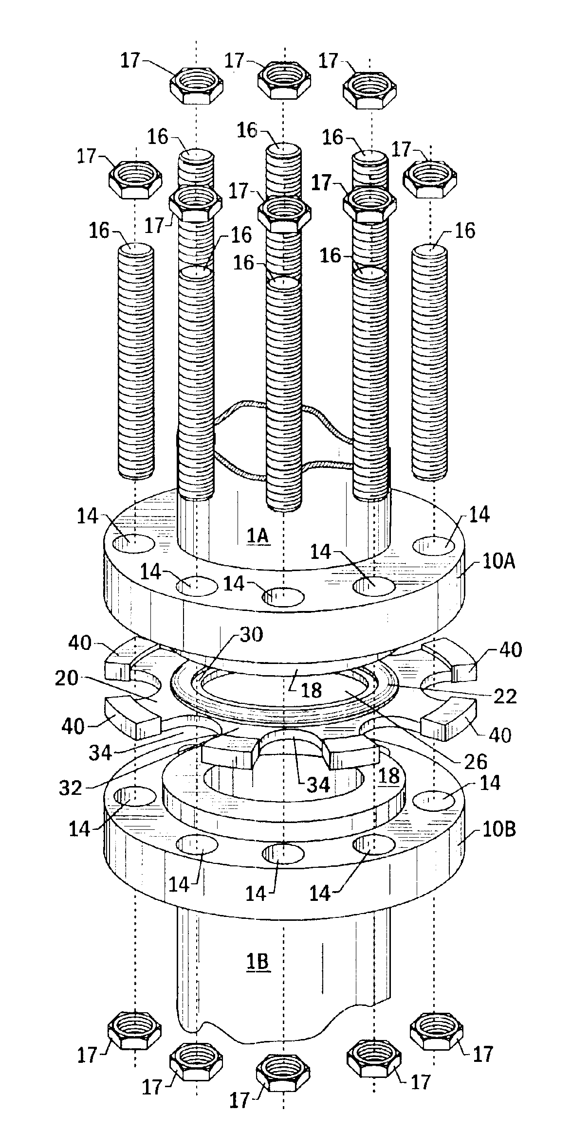
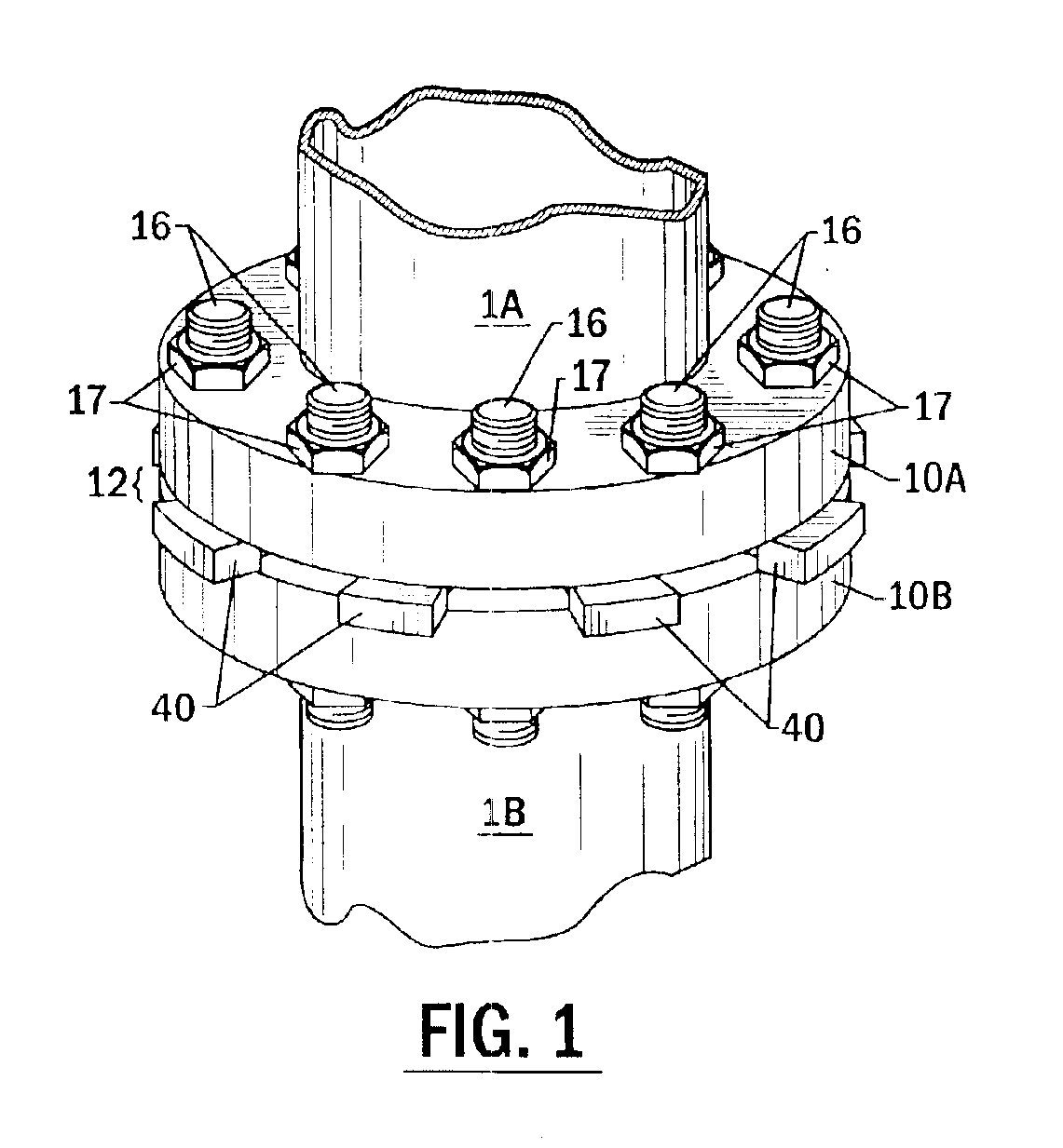
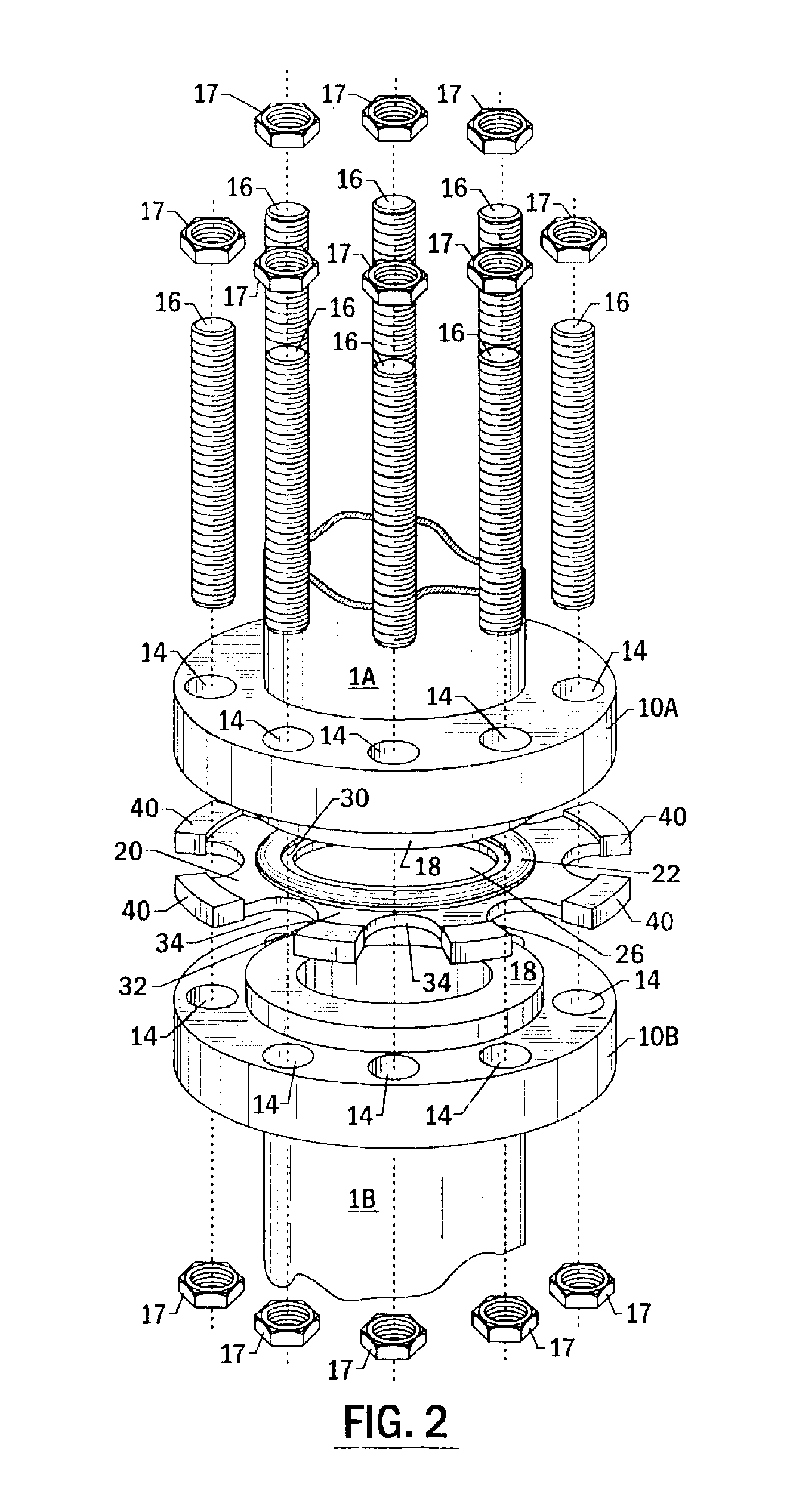
In a preferred embodiment of the present invention, achievement of the correct gasket seating stress is accomplished by providing fixed compression stops about the inner and outer sealing surface circumferences. The compression stops are sized to withstand the flange compressive forces resulting from the assembly process for each given flange pressure class.

Referring now to FIG. 1, a preferred embodiment of a constant seating s...


PUM


Abstract

A gasket system for sealed interfaces utilizes a carrier ring having inner and outer compression stops to account for and control flange rotation effects in order to achieve a uniform and constant gasket seating stress across the sealing region. The inner compression stop provides a fixed fulcrum for flange rotation. The inner and outer compression stops have different heights, dependent upon the characteristic flange rotation, that allow the orientation of the sealing material to be angularly matched to the flange side profile and that allow the sealing material to be fully captured within the sealing region upon full compression, minimizing creep relaxation. A visual compression indicator on the circumference of the carrier ring permits assembly of the interface without the use of specialized or calibrated tools.

Description

FIELD OF THE INVENTIONThe present invention relates generally to sealing systems for gasketed connections, and particularly to a gasket system applicable to flanged joints that is designed to achieve and maintain a constant and uniform gasket seating stress in flanged connections.BACKGROUND OF THE INVENTIONThe principal problem encountered in designing and operating effective gasketed connections is seal failure and the leakage associated therewith. Leakage from gasketed joints can be attributed to one or more of five root causes, including (a) sealing surfaces that do not meet the minimum physical conditions necessary to effect a seal, (b) insufficient gasket seating stress to effect a seal, (c) excessive gasket seating stress which results in damage to the sealing components, (d) a reduction in gasket stress due to flange rotation or in-service creep relaxation of the gasket sealing material, and (e) incompatibility of the gasket sealing material with the sealed fluid or the opera...

Claims


Application Information

Patent Timeline
Patent Type & Authority Patents(United States)
IPC IPC(8): F16L17/06F16L17/00F16BF16L23/00F16L23/16
CPCF16L23/003F16L23/18F16L23/16Y10T403/645F16B2200/506
Inventor JENCO, JOHN MICHAEL
Owner JJENCO
Why Eureka
Try Eureka