Optical polarity modules and systems

a technology of optical polarity modules and systems, applied in the field of optical fiber interconnection modules, can solve problems such as system problems

Inactive Publication Date: 2005-03-22
CORNING OPTICAL COMM LLC
View PDF5 Cites 161 Cited by
  • Summary
  • Abstract
  • Description
  • Claims
  • Application Information

AI Technical Summary

Problems solved by technology

System problems can occur when the MTP assembly is used in an interconnect construction.

Method used


Image

  • Optical polarity modules and systems
  • Optical polarity modules and systems
  • Optical polarity modules and systems

Examples


Embodiment Construction

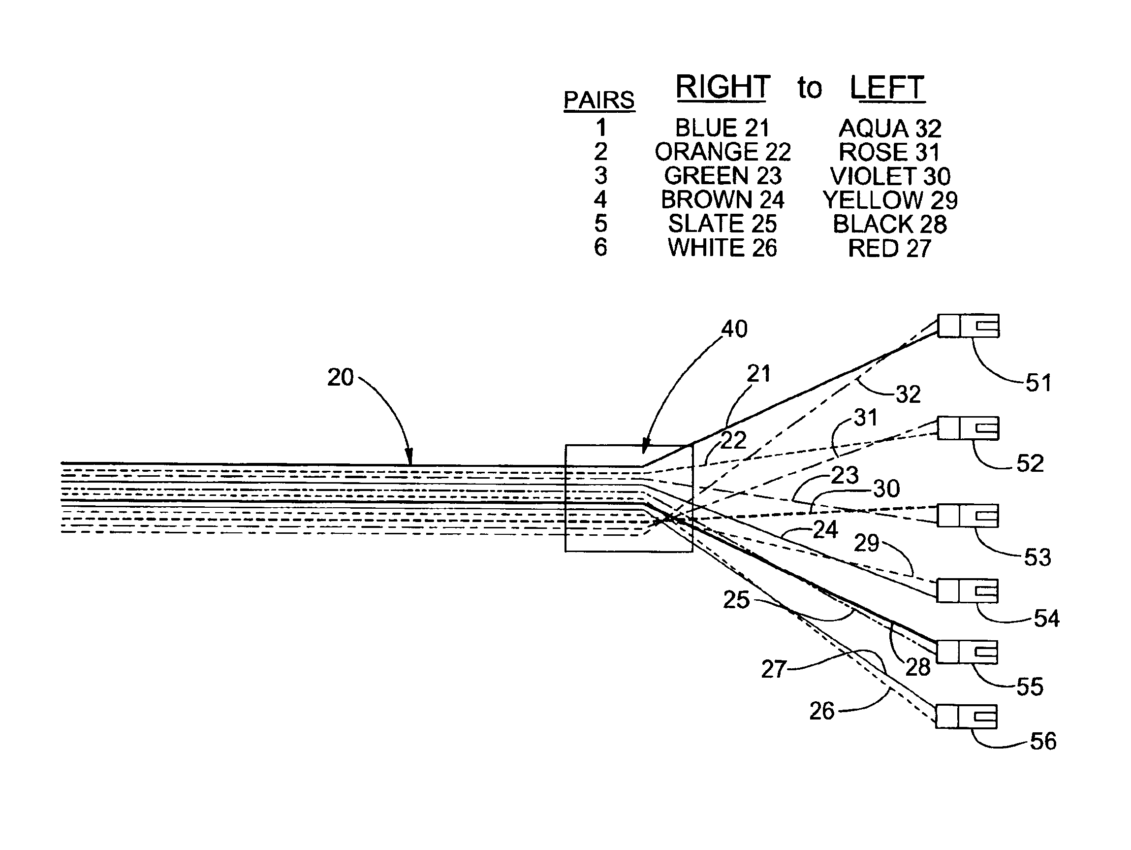
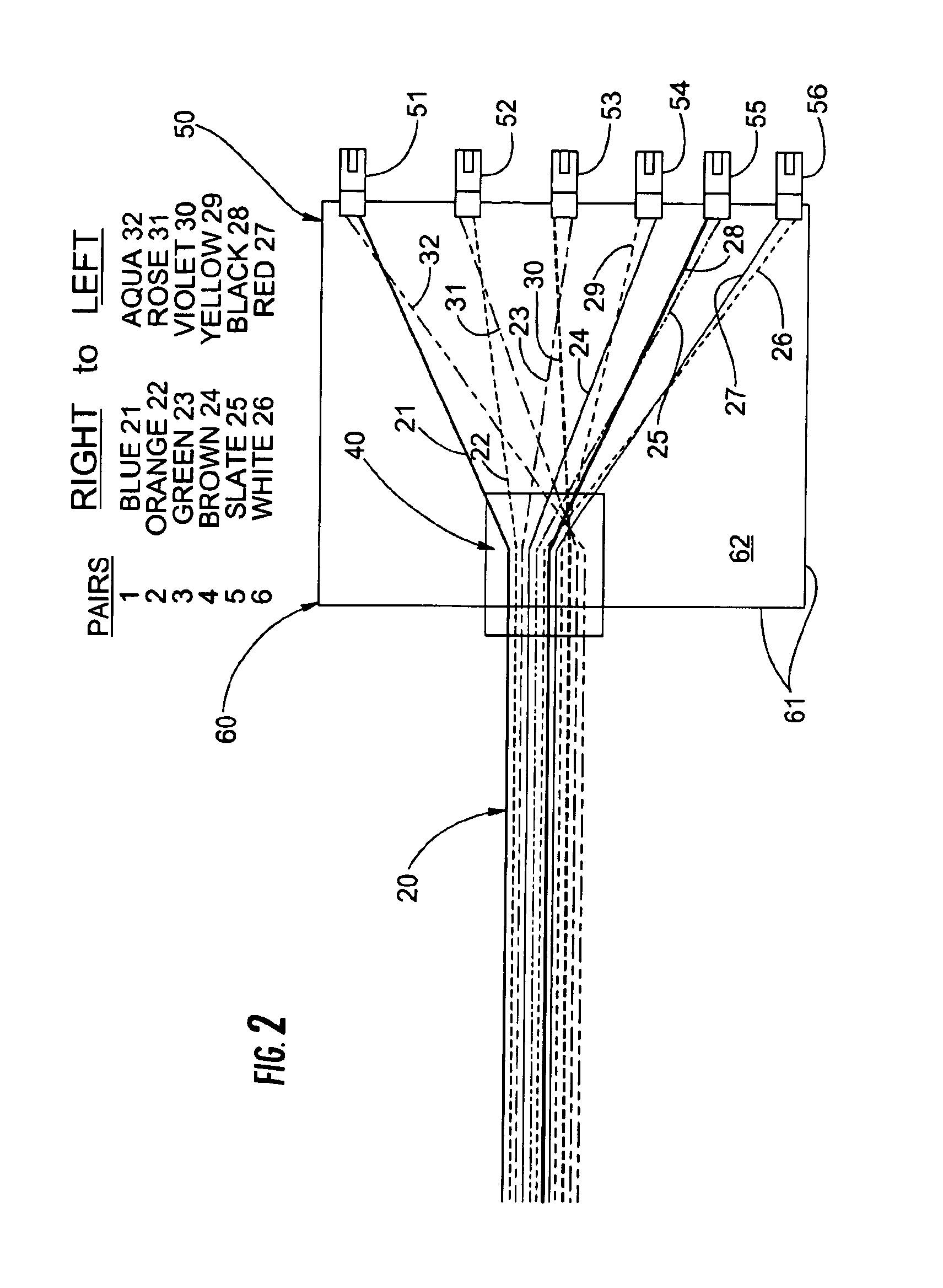
An embodiment of the present invention is an optical networking module for use with an optical fiber ribbon, for example having twelve optical fibers, connected to an MTP or MPO optical connector. FIG. 2 illustrates an exemplary module 60 according to the present invention. Module 60 is optically associated with an optical fiber ribbon 20, for example, having twelve distinctly colored optical fibers 21-32 disposed in a matrix.

Module 60 includes an enclosure defining walls 61 and a cavity 62 within the walls for receiving and supporting optical fibers and connectors.

Module 60 also includes an optical interconnection section having an optical connector. The preferred connector is an MTP or MPO connector 40. Connectors 40 are epoxy and polish compatible multi-fiber connectors, for example, part of Corning Cable Systems' LANScape® solution set. The epoxy and polish connector is a twelve-fiber connector achieving very high density in a small space, it contains multiple optical paths, the...


PUM


Abstract

A universal breakout harness for reversing the polarity of optical fibers includes a multi-fiber connector having a plurality of optical paths, an optical ribbon having a plurality of optical fibers disposed in the optical paths of the multi-fiber connector, and a plurality of optical fiber connectors opposite the multi-fiber connector defining a plurality of pairs of optical fiber paths. The optical fibers are separated and routed between the optical paths of the multi-fiber connector and the pairs of optical paths defined by the plurality of optical fiber connectors such that the optical fibers in at least one of the pairs of optical paths are selected from optical fibers disposed in optical paths of the multi-fiber connector that are not immediately adjacent to each other. The universal breakout harness is used in methods of implementing reverse-ribbon positioning in a cabling system and transitioning ribbon cabling into multiple duplex systems.

Description

FIELD OF THE INVENTIONThe present invention relates to optical fiber interconnection modules, for example, to interconnection modules for use in a local area network (LAN).BACKGROUND OF THE INVENTIONConventional fiber optic cables comprise optical fibers that conduct light which is used to transmit voice, video, and data information. An optical ribbon includes a group of optical fibers that are coated with a ribbon common layer, which common layer may be of the ultraviolet (UV) light curable type. Typically, such a ribbon common layer is extruded about a group of individually colored optical fibers that have been arranged in a planar array, and is then irradiated with a UV light source that cures the ribbon common layer. The cured ribbon common layer protects the optical fibers and generally aligns the respective positions of optical fibers in the planar array. Optical fiber ribbons can be connected to multi-fiber connectors, for example, MTP connectors. MTP connectors can be used i...

Claims


Application Information

Patent Timeline
Patent Type & Authority Patents(United States)
IPC IPC(8): G02B6/38G02B6/44
CPCG02B6/4471G02B6/3885G02B6/3851G02B6/3825G02B6/3831G02B6/3897
Inventor DEL GROSSO, STEVEN C.SHOOK, JR., LARRY K.UGOLINI, ALAN W.
Owner CORNING OPTICAL COMM LLC
Why Eureka
Try Eureka