

Stator for motor
a technology for stators and motors, applied in the direction of windings, dynamo-electric components, magnetic circuit shapes/forms/construction, etc., can solve the problems of connecting parts, affecting the efficiency of winding cooling, and increasing the size of coil ends, so as to prevent the size increase of windings, prevent undesired shift or removal of connecting parts, and efficiently cool windings
- Summary
- Abstract
- Description
- Claims
- Application Information
AI Technical Summary
Benefits of technology
Problems solved by technology
Method used
Image

Examples
first embodiment
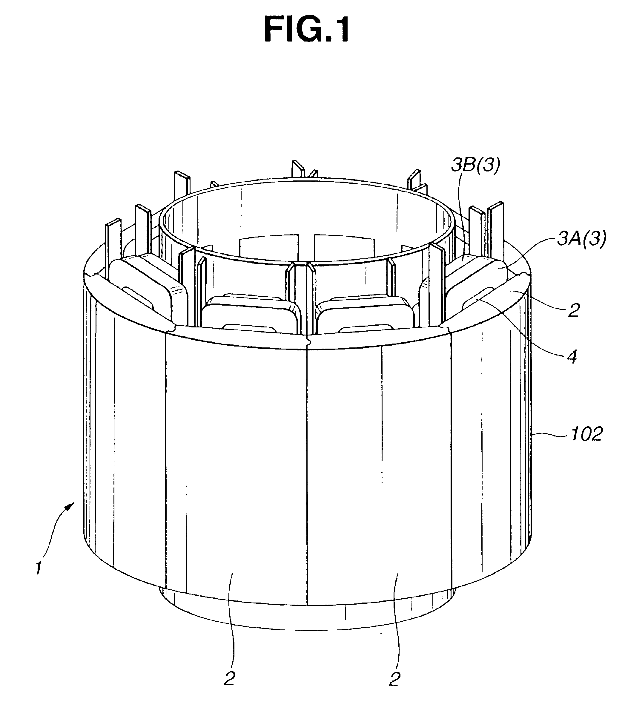
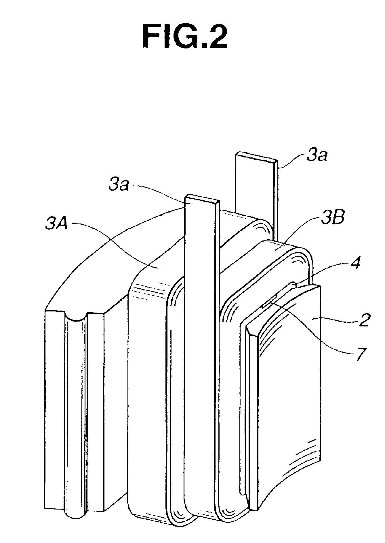
FIGS. 1˜6 show a stator of a motor according to the present invention. FIG. 1 shows a stator made up of a plurality of core segments in perspective, and FIG. 2 shows one core segment for one pole in a state having windings.
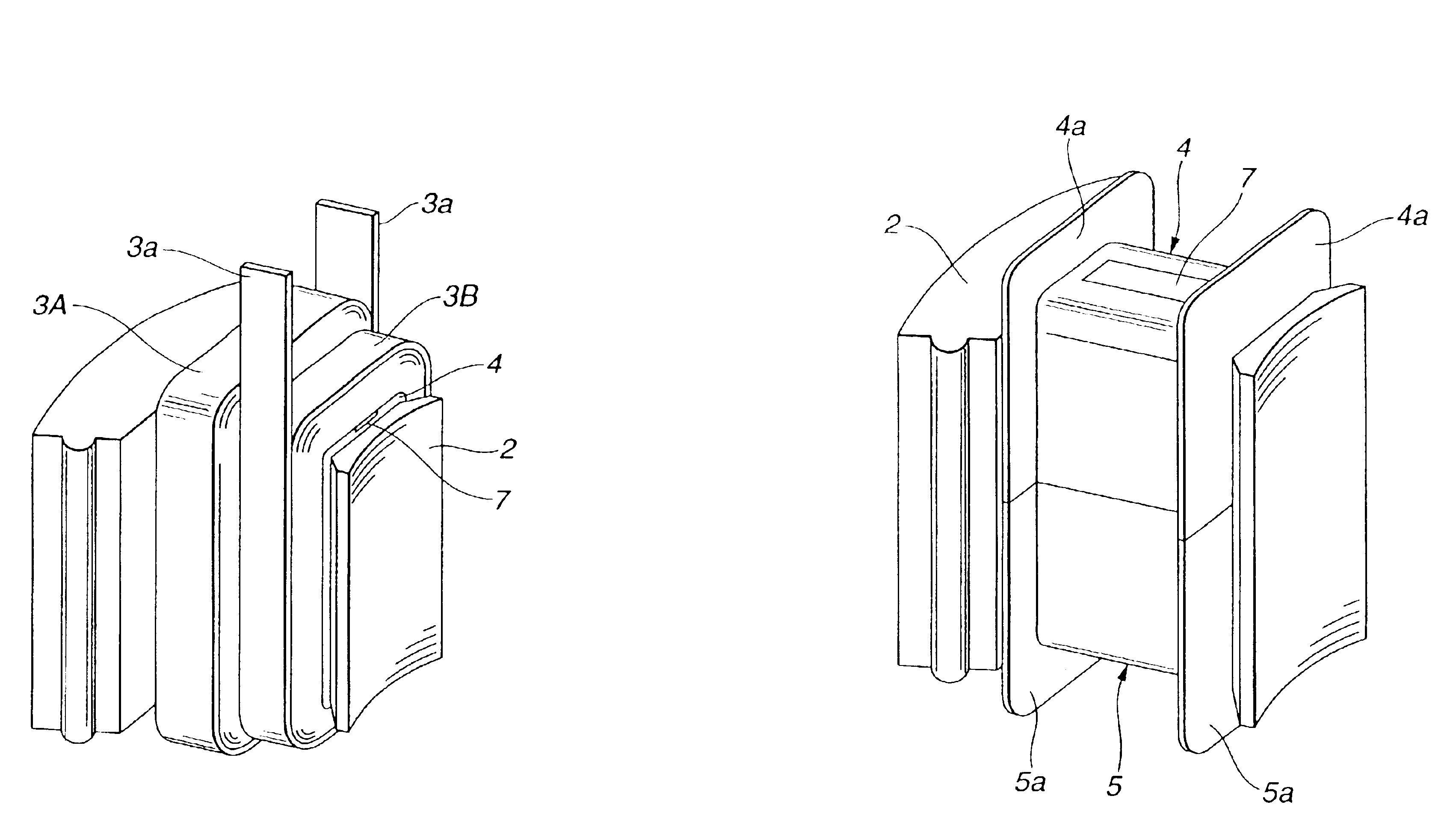
A stator 1 for a motor in the example shown in FIGS. 1 and 2 is of a segmented type including a plurality of stator segments each including a core segment 2 and a stator winding 3. Core segments 2 each corresponding to one pole are arranged in a circle, and form a segmented stator core 102 of an annular shape. As shown in FIG. 2, each stator winding 3 of this example includes two windings 3A and 3B of flat wires (or rectangular or ribbon wires) 3a covered with insulating film. These core segments 2 are arranged in an annular form, and assembled into the annular stator core 102.
FIG. 3A shows one core segment 2 equipped with an insulating member including end caps 4 and 5. The insulating member is shaped like a bobbin. In the state of FIG. 3A, wire is not yet wound,...
second embodiment
FIGS. 8A and 8B show variations of the In the example of FIG. 8A, a connecting member 11 having a rectangular cross section is formed with four protruding portions 12 protruding from the sides of connecting member 11 in two opposite directions. Protruding portions 12 is formed below the upper surface of connecting member 11, and buried in end cap 4. In the example of FIG. 8B, connecting member 11 is formed with middle wider protruding portions 12A protruding outwards from a middle of the length of connecting member 11 between the two longitudinal ends of connecting member 11. Protruding portions 12A are buried in end cap 4 at a middle position between first and second windings 3A and 3B. In the example of FIG. 8A, there are two terminal protruding portions 12 projecting outward in opposite directions near a first longitudinal end of connecting member 11 and two terminal protruding portions projecting outward in opposite directions near a second longitudinal end of connecting member...
third embodiment
FIG. 9 shows the present invention in which a connecting member 13 is placed obliquely with respect to a winding axis about which first and second windings 3A and 3B are wound. The longitudinal direction of connecting member 13 is not parallel to the winding axis of first and second windings 3A and 3B. Connecting member 13 has at least one side surface 13a extending obliquely with respect to the winding axis, or the radial direction of the annular stator 1 shown in FIG. 1. The outside surface of connecting member 13 is flush with the outside surface of end cap 4 as in the preceding embodiments.
In the example shown in FIG. 9, connecting member 13 is not rectangular but in the shape of a parallelogram having two long parallel sides extending obliquely and two short parallel sides. In the example of FIG. 9, the two parallel short sides extend in parallel to outward flanges 4a to which the winding axis is perpendicular. Connecting member 13 of this example is produced by machining into ...
PUM
 Abstract
Description
Claims
Application Information