Vibratory motors and methods of making and using same

a technology of vibrating motors and motors, applied in piezoelectric/electrostrictive/magnetostrictive devices, piezoelectric/electrostriction/magnetostriction machines, electrical apparatus, etc., can solve the problems of complex assembly and reliability, excessive cost for many applications, and insufficient precision of motor motion, so as to improve performance and reduce tolerances , the effect of improving the ease of system design

Inactive Publication Date: 2005-03-22
ELLIPTEC RESONANT ACTUATOR
View PDF78 Cites 49 Cited by
  • Summary
  • Abstract
  • Description
  • Claims
  • Application Information

AI Technical Summary

Benefits of technology

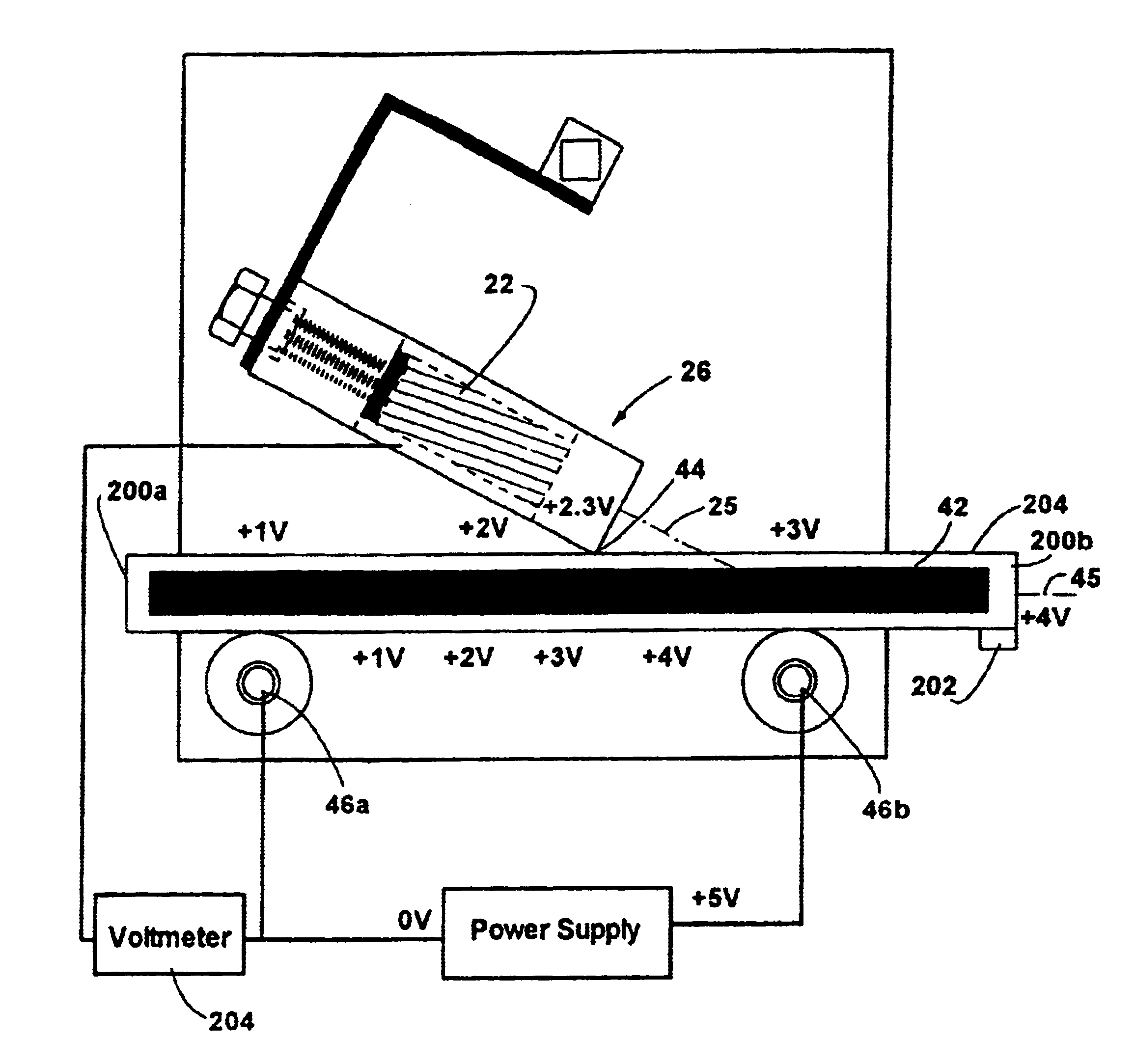
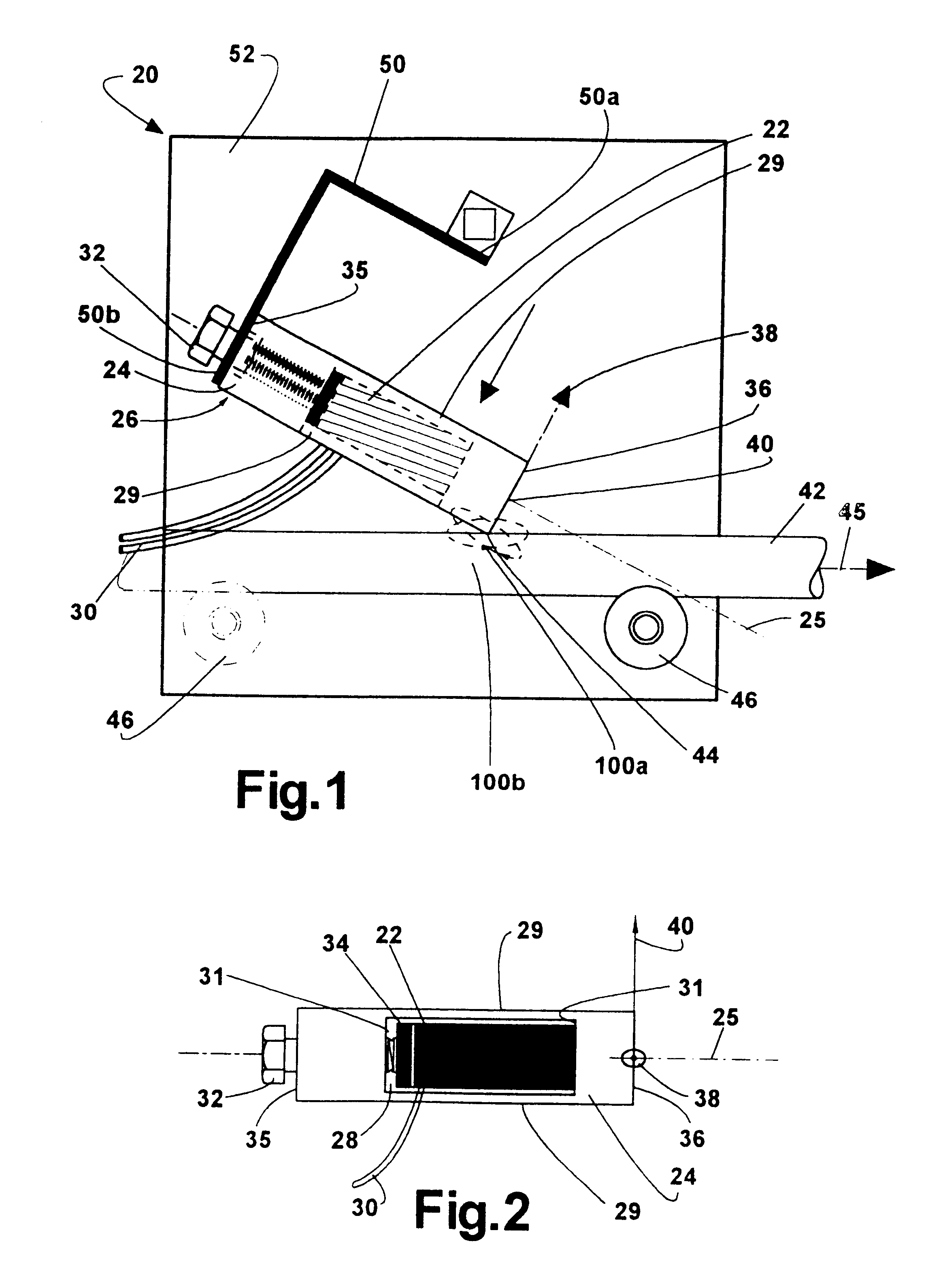
The motion at a distal edge 44 at a distal end 36 of the resonator is typically greatest and is preferably used, although other locations on the motor can be used in some specific embodiments. The opposing end of the motor is the proximal end 35. The result is the distal edge moves in an elliptical path resulting from a combination of at least two vibration modes when the motor is excited by a single signal at a first frequency. The motor is further configured such that a second driving frequency excites two resonant vibration modes in the motor so that the predetermined point on the motor rotates in an elliptical path in an opposite direction as the first elliptical path. A single piezoelectric element and resonator are thus driven by a single frequency to generate a first elliptical motion at a predetermined location on the vibratory motor. The piezoelectric element is driven at a second frequency to excite two resonant vibration modes of the vibratory motor that cause the predetermined location to move in a second elliptical motion in a different, and preferably opposite direction to the first elliptical motion, sufficient to move the driven element a desired distance. The two elliptical motions are typically not overlapping. The motion can be achieved at various locations on the motor, in varying amplitudes and directions, and that allows a variety of arrangements in which the motor can drive other elements.
In one embodiment, a resonator has a longitudinal axis with an opening partially defined by two sidewalls on opposing sides of the longitudinal axis and two opposing end walls on the longitudinal axis. A piezoelectric element is held in compression by the opposing end walls, with each of the sidewalls being stressed beyond its elastic limit to hold the piezoelectric element in compression. The resonator has a selected contacting portion, which moves in a first elliptical motion when the piezoelectric element is excited by the various electrical signals described herein. There are advantages if the sidewalls are curved, and if at least one of the end walls or two opposing sides of the piezoelectric element that engage the end walls have edges that are inclined to facilitate press-fitting the piezoelectric element into the opening and wherein the piezoelectric element is press-fit between the end walls. The sidewalls can be curved to bow away from the piezoelectric element, or toward the piezoelectric element. Further, a portion of an elastic element for supporting the resonator can be interposed between one of the end walls and the piezoelectric element.

Problems solved by technology

While the conventional electromagnetic motors are relatively inexpensive, there are a large number of moving parts which complicates assembly and reliability, and the low power and need for a gearbox not only limits their application but also makes the cost excessive for many applications.
Moreover, these motors are too big, not very precise in their motion, and are noisy.
When the resonator is brought into contact with a body, these vibrations generate frictional forces in the contact area with the body and cause the body to move.
Various cumbersome and expensive designs have been used to obtain useful forces and motions from these small vibratory motions.
These motors typically are based on a disc shaped design and are expensive to produce.
The shape and the cost of these motors limit their application.
Since these motors require a sawtooth or similar shaped waveform to operate, they require complex electronics that increase the cost of such motors.
The resulting electronics are complex and expensive, and it is difficult to use the figure-eight motion to create useful motion of an object.
This requires two sets of drivers, two sets of electronic driving systems, an electronic system that will reverse the phase of each driver, and the basic design places limitations on the locations of components.
Unfortunately, this actuator requires two sets of electronics to drive the motor in opposing directions, and has two sets of driving piezoelectric plates, resulting not only in a large number of parts but also greatly increasing the complexity of the system and resulting in significant costs for these type of motors.
The motor also has limited power because the driving frequency is selected to be between two resonant frequencies.
Again though, there are a number of electronic connections and many parts to achieve this motion, resulting in a high cost for this type of motor.

Method used


Image

  • Vibratory motors and methods of making and using same
  • Vibratory motors and methods of making and using same
  • Vibratory motors and methods of making and using same

Examples


Embodiment Construction

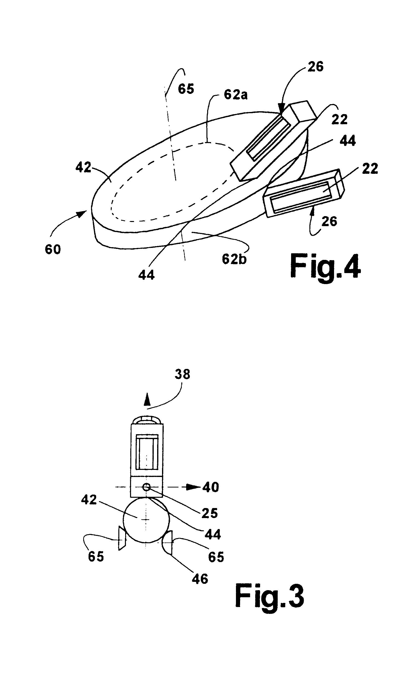
Several embodiments of the motor of this invention will be described, following which a number of theoretical and practical operational and design aspects of the motors are described. Referring to FIGS. 1-3, and as described in detail at various locations, the piezoelectric motor assembly 20 has an element that converts electrical energy into macroscopic mechanical motion. This is achieved by using a single electrical signal to generate at least two vibration motions at a predetermined location of a vibration element. The at least two vibration motions result in an elliptical motion at the predetermined location. The elliptical motion is selected to cause the vibrating element to engage a driven element during a time corresponding to at least a portion of travel in direction of a long axis of the ellipse, and to disengage or slide over the driven element during a time corresponding to travel in the opposite direction. A second, single frequency results in a second elliptical motion ...


PUM


Abstract

A single piezoelectric is excited at a first frequency to cause two vibration modes in a resonator producing a first elliptical motion in a first direction at a selected contacting portion of the resonator that is placed in frictional engagement with a driven element to move the driven element in a first direction. A second frequency excites the same piezoelectric to cause two vibration modes of the resonator producing a second elliptical motion in a second direction at the selected contacting portion to move the driven element in a second direction. The piezoelectric is preloaded in compression by the resonator. Walls of the resonator are stressed past their yield point to maintain the preload. Specially shaped ends on the piezoelectric help preloading. The piezoelectric can send or receive vibratory signals through the driven element to or from sensors to determine the position of the driven element relative to the piezoelectric element or resonator. Conversely, the piezoelectric element can receive vibration or electrical signals passed through the driven element to determine the position of the driven element. The resonator is resiliently urged against the driven element, or vice versa. Plural resonators can drive common driven elements.

Description

BACKGROUND OF THE INVENTIONTo move small components, electromagnetic motors are often used because they are relatively inexpensive. The electromagnetic motors rotate very quickly and can only apply a low force, so they are always used with a gearbox that provides the slower motion and increased power necessary for practical applications. It should be noted that the movement of driven elements referred to in this disclosure refers to a translation or rotary motion in a common direction, and does not included motion that merely moves a part alternatively back and forth to shake the part without any net movement. While the conventional electromagnetic motors are relatively inexpensive, there are a large number of moving parts which complicates assembly and reliability, and the low power and need for a gearbox not only limits their application but also makes the cost excessive for many applications. Moreover, these motors are too big, not very precise in their motion, and are noisy. The...

Claims


Application Information

Patent Timeline
Patent Type & Authority Patents(United States)
IPC IPC(8): H01L41/09H02N2/00H02N2/04H02N2/08
CPCH01L41/0906H10N30/202
Inventor MAGNUSSEN, BJOERNVARADI, PETERHAGEMANN, BENJAMINSCHOFIELD, STEVENDAVIDSON, ERICK M.
Owner ELLIPTEC RESONANT ACTUATOR
Why Eureka
Try Eureka