Test instrument with multiple analog modules

a test instrument and analog module technology, applied in the field of electronic device testing, can solve the problems of limited number of analog test instruments available for testing, large number of digital test instruments, etc., and achieve the effect of tight synchronization

Inactive Publication Date: 2005-03-22
CREDENCE SYSTEMS
View PDF5 Cites 10 Cited by
  • Summary
  • Abstract
  • Description
  • Claims
  • Application Information

AI Technical Summary

Benefits of technology

[0008]The invention is useful in a number of potential applications. First, an SOC IC requiring the testing of both digital and analog pins has many more digital pins to be tested than analog pins. A typical digital pin to analog pin ratio is 100:1. As a result, in a given test apparatus, the number of digital test instruments far outnumbers analog test instruments, and the number of analog test instruments available for testing is limited. The analog test instrument according to the invention provides testing flexibility in such test environments because it can test one analog pin independently from the others.
[0009]Second, the testing of analog pins of SOC ICs typically involves structural testing, which allows testing of pins to be carried out at the same time even though they might have different dynamic features. With the invention, this type of testing can be performed efficiently because: (i) up to four analog pins may be tested with a single instrument; (ii) testing of the four analog pins with a single instrument is carried out such that each analog pin is tested independently with respect to the other three, and (iii) analog modules for testing analog pins with different dynamic features may be mounted in a single instrument.
[0011]A fourth potential application is analog pin testing that requires very tight synchronization. With the invention, the clocks of the four independent modules are derived from a common source that is fully synchronous and phase aligned with the rest of the system. As a result, the clocks of the four independent modules are fully synchronized and phase aligned with each other as well as with the rest of the system, and permit generation of test signals that are very closely matched in phase.

Problems solved by technology

As a result, in a given test apparatus, the number of digital test instruments far outnumbers analog test instruments, and the number of analog test instruments available for testing is limited.

Method used


Image

  • Test instrument with multiple analog modules
  • Test instrument with multiple analog modules
  • Test instrument with multiple analog modules

Examples


Embodiment Construction

trates an internal bus between a bus interface and a system monitoring device;

[0018]FIG. 6A illustrates a reset signal supplied to a clock divider implemented in the analog instrument of FIG. 2;

[0019]FIG. 6B is a block diagram of a circuit that generates the reset signal of FIG. 6A; and

[0020]FIG. 7 is a flow diagram showing the configuration process of the analog instrument of FIG. 2.

DETAILED DESCRIPTION

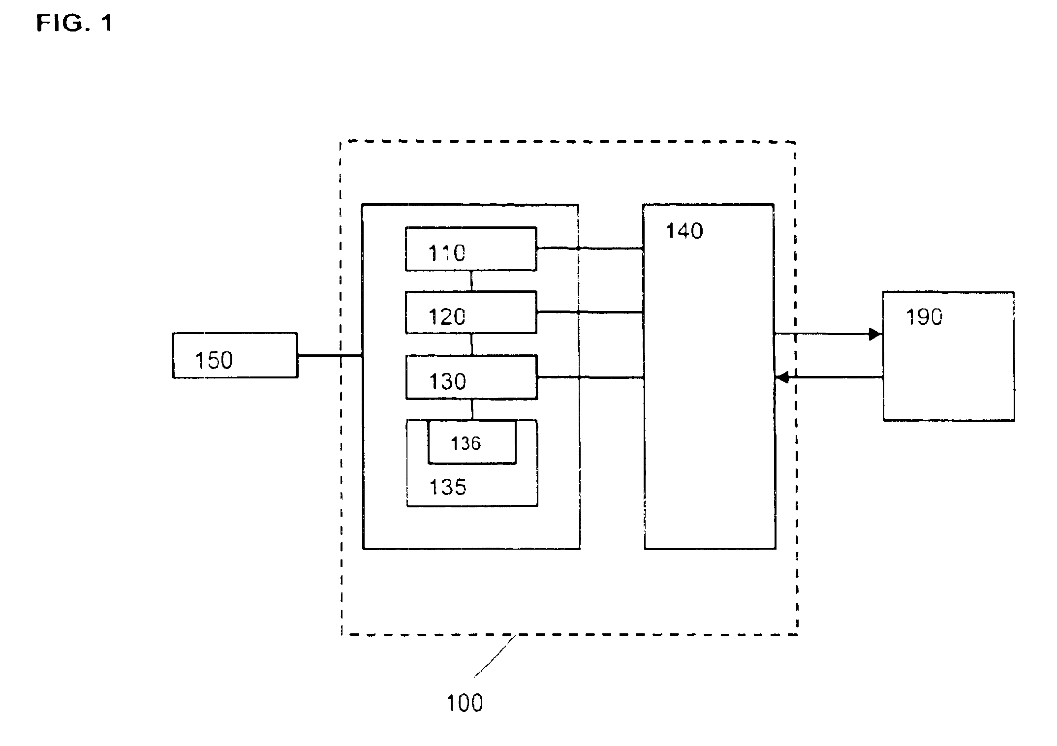
[0021]FIG. 1 is a block diagram of a tester 100 that is used in testing electronic devices. The tester 100 includes a number of slots in which a number of instruments are inserted. The instruments include a device power supply (DPS) 110 for supplying power to a device under test (DUT) 190, analog test instruments 120 for supplying test signals to analog pins of the DUT 190 and receiving response signals from the analog pins, digital test instruments 130 for supplying test signals to digital pins of the DUT 190 and receiving response signals from the digital pins, a test head interfac...


PUM


Abstract

An analog test instrument used in an apparatus for testing electronic devices has multiple analog modules for supplying test signals to analog pins of a device under test and receiving response signals from the analog pins. The analog modules may be of the same type or of different types. The analog test instrument also has programmable devices that control in an independent manner the triggering, clocking, and generation of the test signals supplied by each of the analog modules, so that test signals of various timings, speeds and waveforms may be generated.

Description

BACKGROUND OF THE INVENTION[0002]1. Field of the Invention[0003]The present invention relates generally to electronic device testing, and more particularly, to integrated circuit (IC) testing using analog test instruments.[0004]2. Description of the Related Art[0005]Today's SOC (System On a Chip) ICs implement in a single device functions that used to be supported in a chip set. As a result, a single IC device is likely to have both analog and digital functionalities, including audio and video signal generation and acquisition, digital signal processing, and high speed serial interfaces. The testing of these devices requires both digital instruments for testing digital pins and analog instruments for testing analog pins.SUMMARY OF THE INVENTION[0006]The invention provides an analog test instrument that is capable of simultaneously testing multiple analog pins of a device under test. The analog test instrument includes multiple analog modules for supplying test signals to the analog ...

Claims


Application Information

Patent Timeline
Patent Type & Authority Patents(United States)
IPC IPC(8): G01R31/26G01R31/02G01R31/3163G01R31/319
CPCG01R31/31917G01R31/3163
Inventor RICCA, PAOLO DALLA
Owner CREDENCE SYSTEMS
Why Eureka
Try Eureka