Variable rate modulator

a modulator and variable rate technology, applied in the direction of oscillator generators, digital transmission, pulse automatic control, etc., can solve the problems of significant deterioration in the quality of the television image caused by jitter, and achieve the effect of high resolution

Inactive Publication Date: 2005-03-22
AVAGO TECH WIRELESS IP SINGAPORE PTE
View PDF19 Cites 5 Cited by
  • Summary
  • Abstract
  • Description
  • Claims
  • Application Information

AI Technical Summary

Problems solved by technology

When the signals illustratively provide television information, the jitter produces a significant deterioration in the quality of the television image.

Method used


Image

  • Variable rate modulator
  • Variable rate modulator
  • Variable rate modulator

Examples


Embodiment Construction

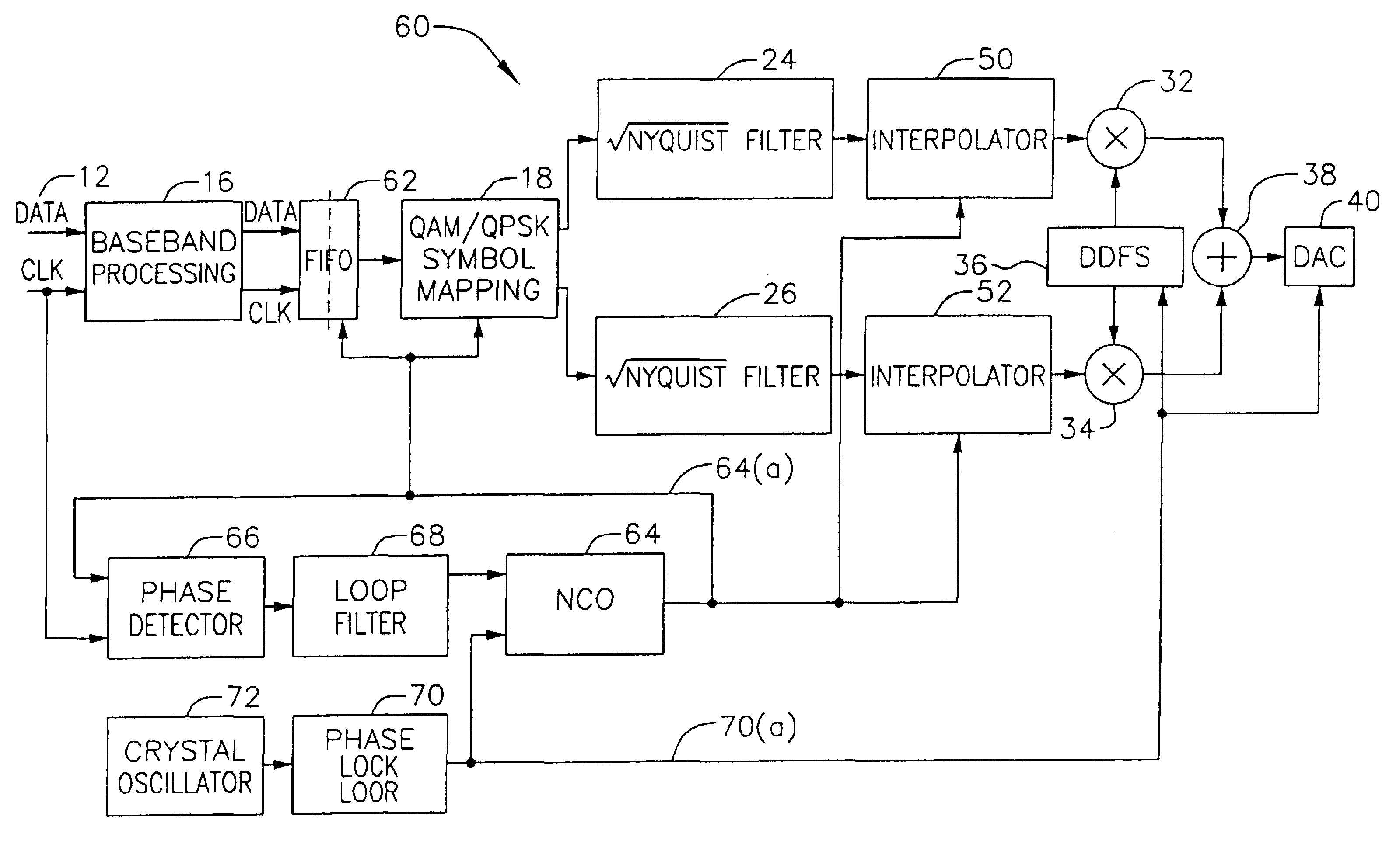
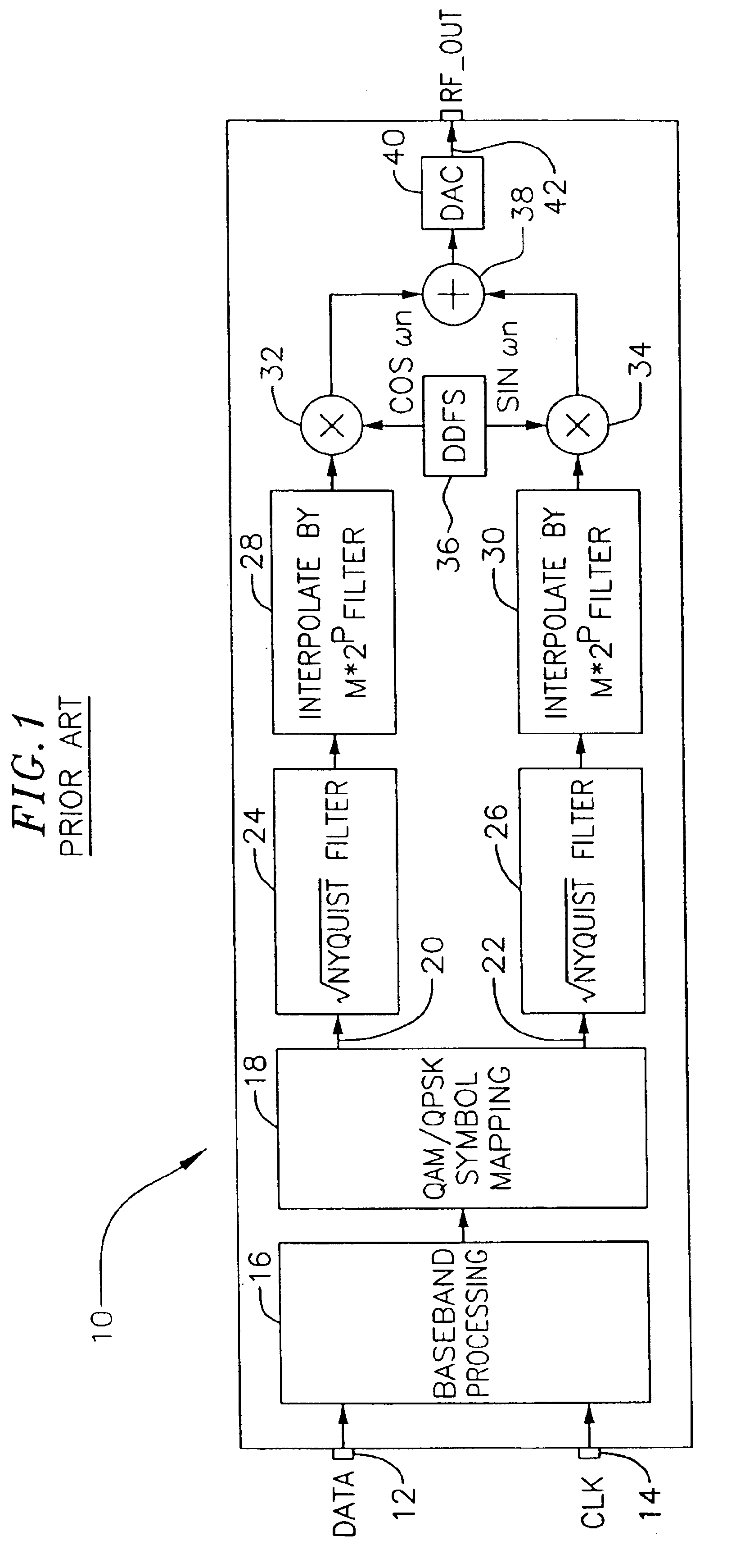
FIG. 1 shows a system, generally indicated at 10, of the prior art for transmitting digital data at a variable frequency, for processing the digital data and for converting the digital data at a fixed frequency to analog data. In the system 10, the digital data is provided a the variable frequency on a line 12 and clock (CLK) signals are provided on line 14 at the same variable frequency. This variable frequency may vary through a rate such as approximately 10-40 megabits per second. Several processing functions are then performed on the data in a well known manner and are indicated by stage 16 designated as baseband processing. For example, these processing functions may include a data scrambler, an error detector and a stage operative on a preamble in the data to achieve synchronization.

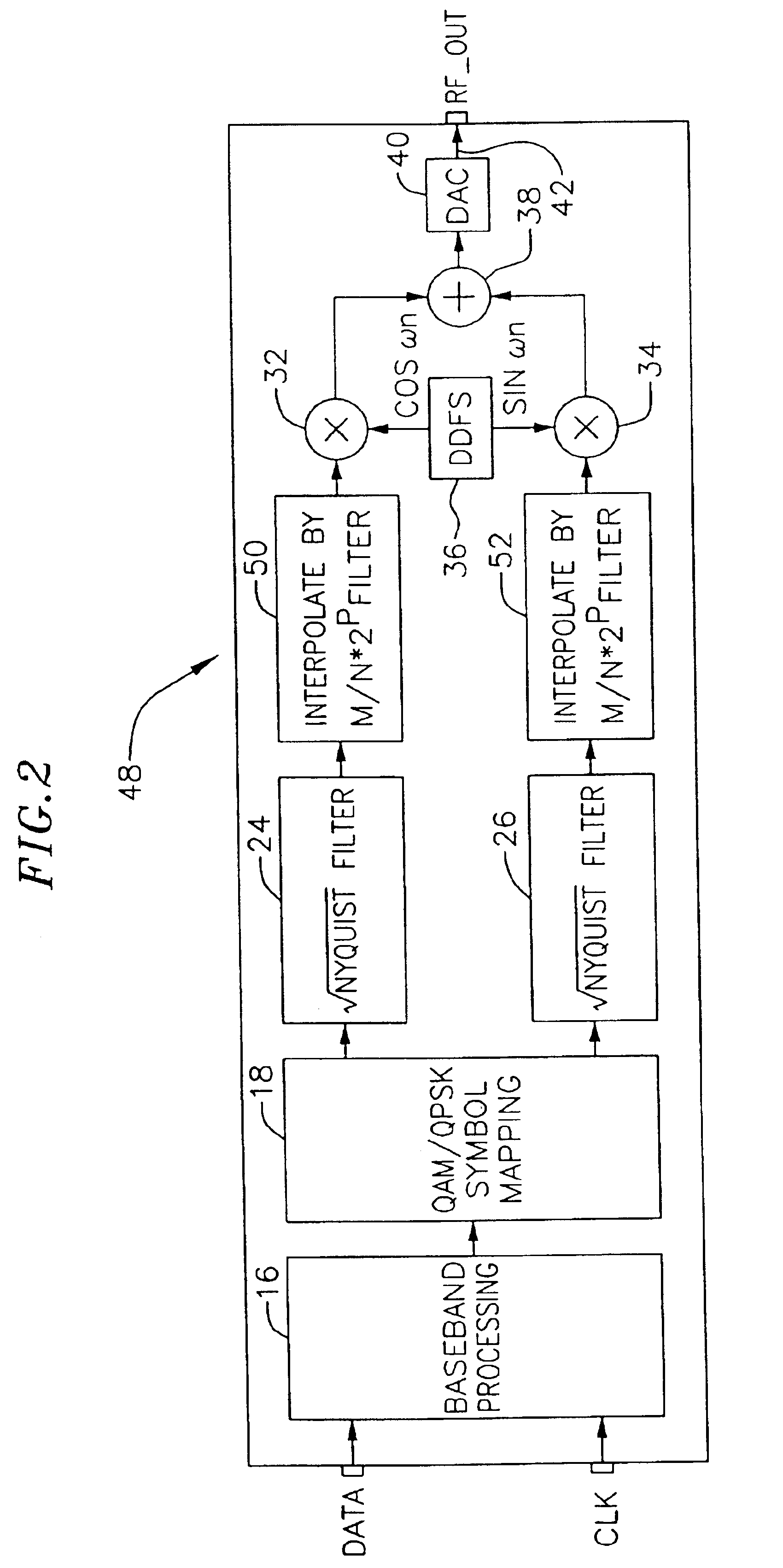
The signals from the stage 16 are then introduced to a stage 18 which may be constructed in a well known manner. The stage 18 is designated as QAM (quadrature amplitude modulated) / QPSK (differentia...


PUM


Abstract

Clock signals and digital data signals at a variable frequency are introduced to the input of a FIFO and are passed from the FIFO at a second (or intermediate) frequency controlled by a numerically controlled oscillator. To regulate the frequency of the signals from the numerically controlled oscillator, the phases of the clock signals at the variable frequency are compared in a phase detector with the phases of the signals from the numerically controlled oscillator to generate an error signal. The error signals and the signals at a fixed sampling frequency higher than the intermediate frequency regulate the frequency of the signals from the numerically controlled oscillator and thus the frequency of the digital data signals from the FIFO. The digital data signals from the FIFO are converted to a pair of signals at the second frequency. The pair of signals at the second frequency have individual ones of a plurality of analog levels dependent upon a code indicated by successive pairs of the digital data signals. The signals at the second (or intermediate) frequency modulate a pair of trigonometrically related signals at the fixed sampling frequency. The modulated signals at the fixed sampling frequency are combined and the combined signals are sampled at the fixed sampling frequency to corresponding analog values by a digital-to-analog converter.

Description

FIELD OF THE INVENTIONThis invention relates to a system including a variable rate modulator for (1) varying the rate at which signals are modulated in accordance with variations in the rate of introduction of digital data to the system and (2) processing the modulated signals to provide output signals at a fixed frequency.BACKGROUND OF THE INVENTIONIn recent years, a number of different applications have arisen in which digital signals representing data are processed and the processed signals are then converted to analog signals. For example, such applications have included the transmission of television signals through coaxial lines to homes. In such systems, the digital data is converted to analog signals and the analog signals are then transmitted through coaxial lines to homes of subscribers. Other applications are in microwave links to satellite communications.In a number of the different applications involving the processing of digital data and the conversion of the processed...

Claims


Application Information

Patent Timeline
Patent Type & Authority Patents(United States)
IPC IPC(8): H04L27/34H04L27/36
CPCH04L27/362
Inventor HAWLEY, ROBERT A.JOSHI, ROBINDRA B.LIU, HUAN-CHANG
Owner AVAGO TECH WIRELESS IP SINGAPORE PTE
Why Eureka
Try Eureka