
Image display

a technology of image and frame rate, applied in the field of apparatus and methods, can solve problems such as geometric distortion, and achieve the effect of high frame rate and correcting image distortion

Inactive Publication Date: 2005-03-22
VUZIX
View PDF10 Cites 30 Cited by
  • Summary
  • Abstract
  • Description
  • Claims
  • Application Information

AI Technical Summary

Benefits of technology

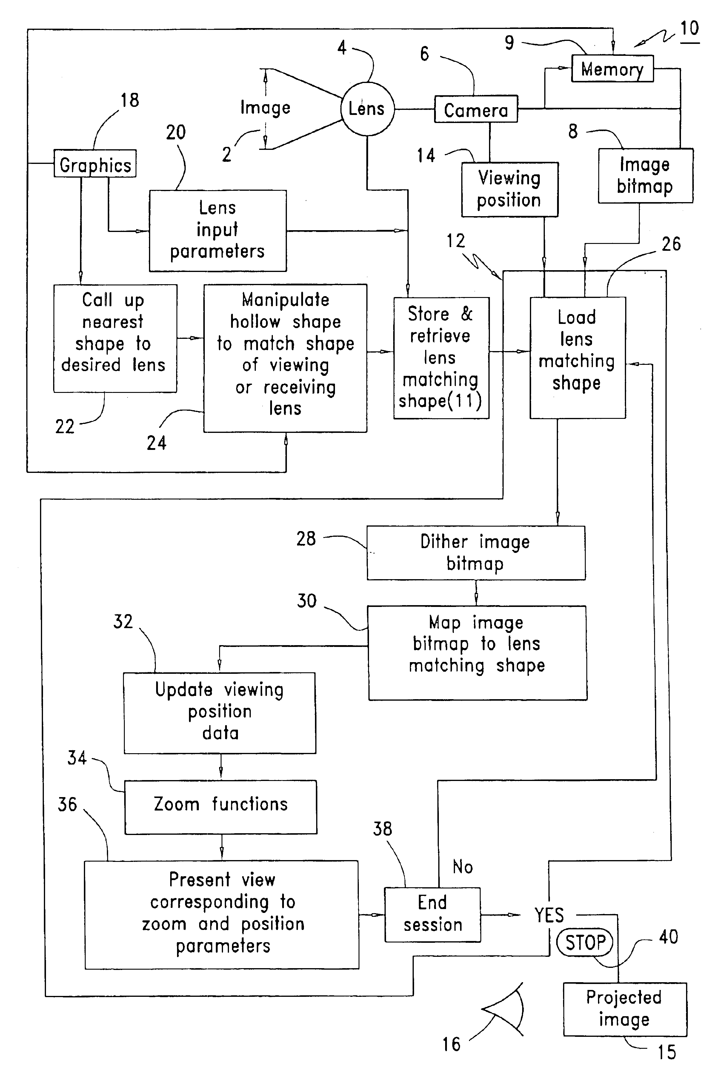
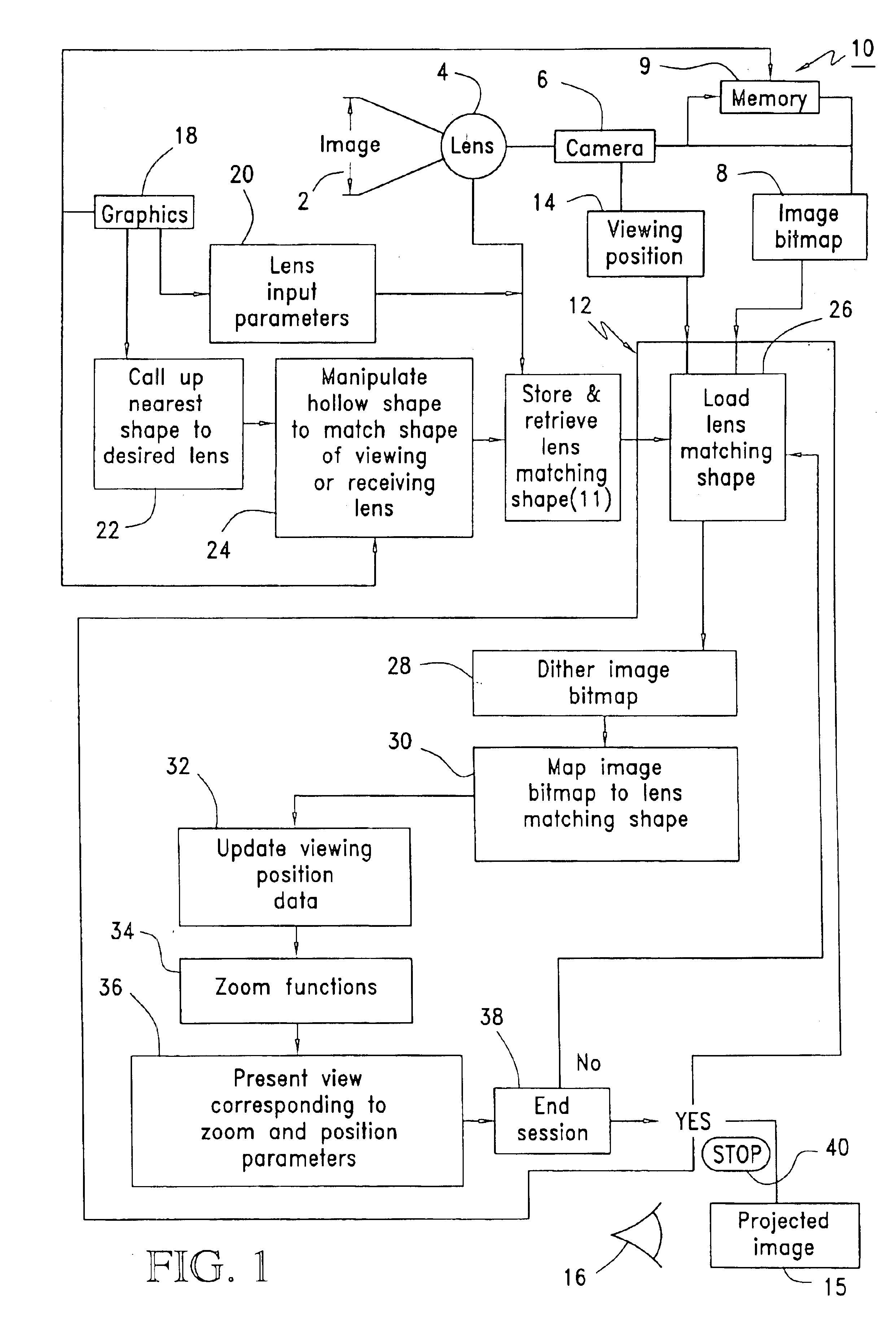
The present invention uses a graphics engine that accepts a shape, referred to hereafter as an effective lens shape, corresponding to the geometry of an original recording lens, an image, and an image-related viewing position. The graphics engine projects the image on the shape and displays a selected portion of the image as seen from the viewing position. The recording lens is often a wide-angle or ultra wide-angle lens.
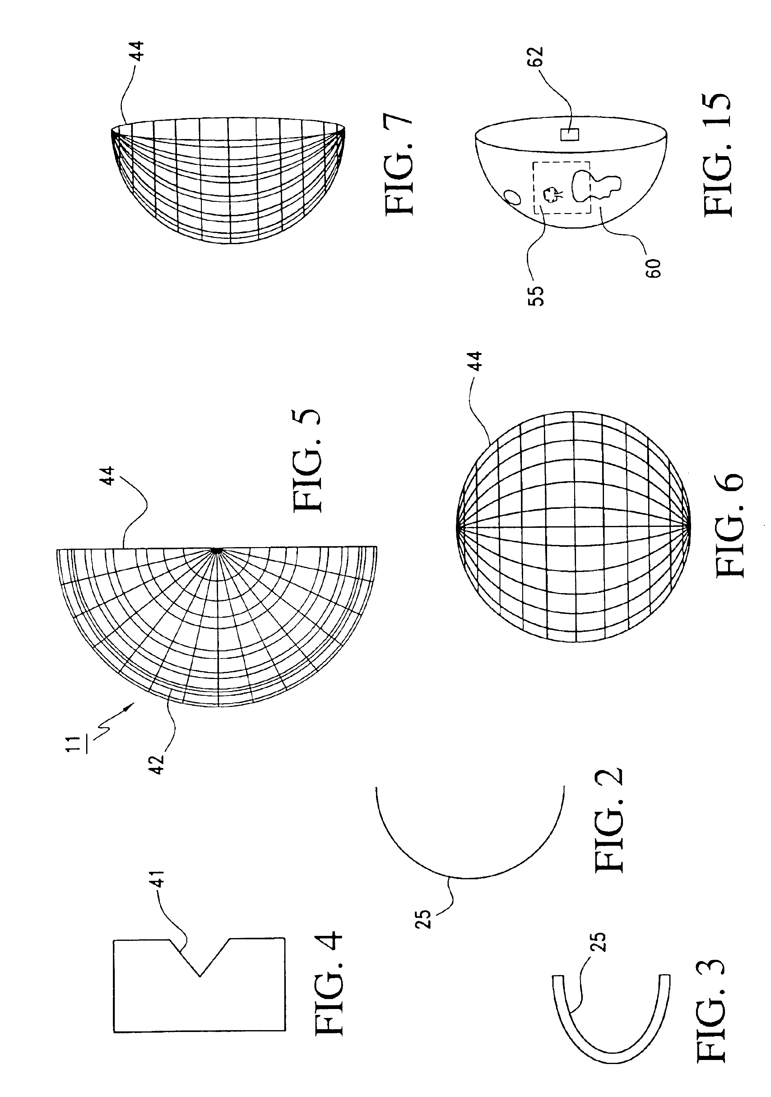
It is important to remember that there is no real physical shape created in this process. The shape is most commonly an array of vertices that is interpreted as a shape by the graphical engine. This method is equivalent to the application of a correction to the recorded coordinates of the image. The recording lens causes the recorded image to be distorted when it is projected onto a plane surface. Geometric distortion occurs because the recording lens is projecting parts of the image from different directions onto a plane surface. The present invention may be applied to a focusing system including those with lenses that have a field of view from less than 180°, such as a 120° lens, to focusing systems that have a field of view greater than 90°.
The photographic image is converted into a bitmap and loaded into memory. The bitmap is rendered onto an effective shape which corresponds to the recording geometry and the original lens shape. Viewing position information is input for software routines that use orientation functions to accommodate changing viewing directions.
The present invention offers the ability to view an environment in real time or non-real time. In non-real time a viewer could stop and “look around” at any given point and time, observing different sections of the mapped image. For real time viewing, a hardware accelerator provides what appears to the viewer to be a natural continuous image by using a sufficiently high frame rate.
The present invention further relates to a method for viewing wide-angle lens photographs without distortion. The photographic image is converted into a bitmap; loaded into memory; an effective shape is created corresponding to the original lens shape, onto which the image bitmap will be rendered; the shape is loaded into memory; the image bitmap mapped or rendered onto the shape in such a way as to correct the distortion in the image when viewed from different positions; and the position information is supplied to software routines that provide for changing views using orientation functions.

Problems solved by technology

Geometric distortion occurs because the recording lens is projecting parts of the image from different directions onto a plane surface.

Method used


Image

  • Image display
  • Image display
  • Image display

Examples


Embodiment Construction

In the present invention an image 2, to be mapped and viewed live or recorded for later viewing, is recorded through a recording lens 4 by a camera 6. The original recording “lens” may consist of a single lens, composite lens, a multiple lens system, or a focusing system. As shown in FIG. 1, there may be one or more lens 4a, 4b. For the sake of simplicity, the recording lens system will be referred to as the recording lens 4. The image 2 may be “live” and altered as it is filmed, it may come from storage, it may be cable broadcast, or it may come from a DVD (digital versatile disk).

Virtual reality technology often uses recording lenses that are a wide-angle lenses. Wide-angle partial panoramic photos, 120 to 180 degree lenses and 360-degree lenses can capture images in a cost-effective manner using either a standard camera or a digital camera. Examples of wide-angle and ultra wide-angle recording lenses include “fisheye” lenses and torus shaped (doughnut) lenses. The problem is that...


PUM


Abstract

The present invention converts a wide-angle lens image into a two dimensional view with reduced distortion and warping. The present invention uses a graphics engine which accepts a shape, an image, and a viewing position. An effective lens shape, corresponding to the recording lens, an image as well as a image-related viewing position is supplied to the graphics engine. The graphic engine projects the image on the effective shape and displays a portion of the image from the viewing position. The recording lens is often a wide-angle lens. The graphics rendering engine maps the wide-angle lens image onto an effective lens shape and displays sections of the mapped image on the shape in a full screen view. Portions of or the entire image are viewable at any one time. Use of acceleration hardware permits frame per second rates of display of up to 60 and greater frames per second. Typical wide-angle recording lenses include “fisheye” lenses and torus shaped (doughnut) lenses.

Description

FIELD OF THE INVENTIONThis invention relates generally to an apparatus and method for displaying images and video created from wide angle or other recording lens systems. Specifically, the present invention uses a graphics-rendering engine (graphics engine) to accept an effective lens shape, an image, and a viewing position such that the effective lens shape corresponds to the recording geometry and original recording lens system. The graphic engine renders or projects the image on the effective shape and displays a portion of the image from the viewing position thus correcting for distortion created during recording which is particularly evident where images are formed using wide angle lenses or 360 degree panoramic lenses. The graphics engine, viewpoint and size inputs enable the displayed portion of the image to be changed. The contemplated images may be still frame, live video, DVD, broadcast cable or any other images.BACKGROUND OF THE INVENTIONNumerous applications exist for an...

Claims


Application Information

Patent Timeline
Patent Type & Authority Patents(United States)
IPC IPC(8): G06T15/20G06T15/10H04N5/217G06T1/00G06T3/00G06T15/04H04N13/04H04N15/00
CPCG06T15/04H04N5/23238H04N5/217H04N23/81H04N23/698H04N25/61
Inventor TRAVERS, PAULTHIERRY, WESLEY
Owner VUZIX
Learn More