Small spot ellipsometer

Inactive Publication Date: 2005-03-22
THERMA WAVE INC
11 Cites 12 Cited by

AI-Extracted Technical Summary

Problems solved by technology

Unfortunately, the lenses available from LightPath have a relatively high coefficient of thermal expansion, on the order of 8×10⁻⁶/K or roughly ten times greater than fused silica lenses (coefficient on the order of 6×10⁻⁷/K).
Lenses having a high coef...

Benefits of technology

Unfortunately, the lenses available from LightPath have a relatively high coefficient of thermal expansion, on the order of 8×10⁻⁶/K or roughly ten times greater than fused silica lenses (coefficient on the order of 6×10⁻⁷/K). Lenses having a high coefficient of thermal expansion can give rise to problems since they are typically held in fixed lens mounts. More specifically, as the...

Abstract

An ellipsometer capable of generating a small beam spot is disclosed. The ellipsometer includes a light source for generating a narrow bandwidth probe beam. An analyzer is provided for determining the change in polarization state of the probe beam after interaction with the sample. A lens is provided having a numerical aperture and focal length sufficient to focus the beam to a diameter of less than 20 microns on the sample surface. The lens is formed from a graded index glass wherein the index of refraction varies along its optical axis. The lens is held in a relatively stress free mount to reduce stress birefringence created in the lens due to changes in ambient temperature. The ellipsometer is capable of measuring features on semiconductors having a dimensions as small as 50×50 microns.

Application Domain

Light polarisation measurement

Technology Topic

Image

  • Small spot ellipsometer
  • Small spot ellipsometer
  • Small spot ellipsometer

Examples

  • Experimental program(1)

Example

Basic Ellipsometer Configurations
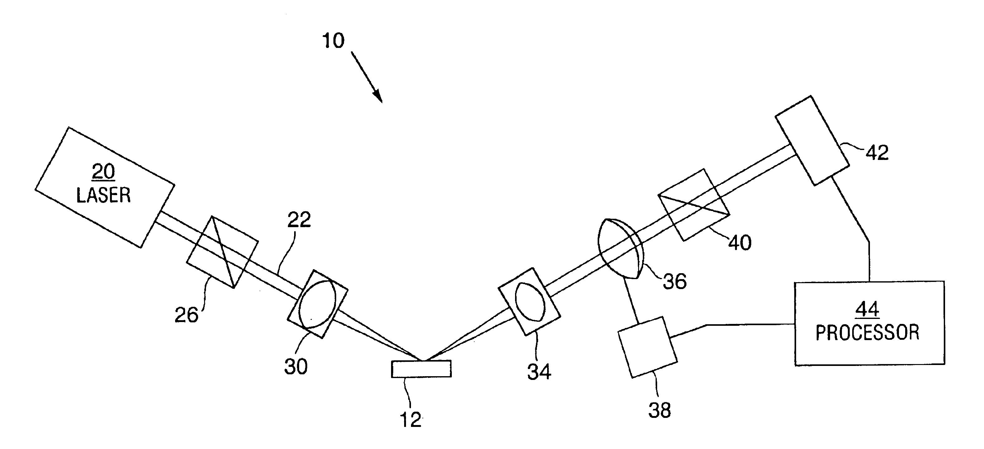
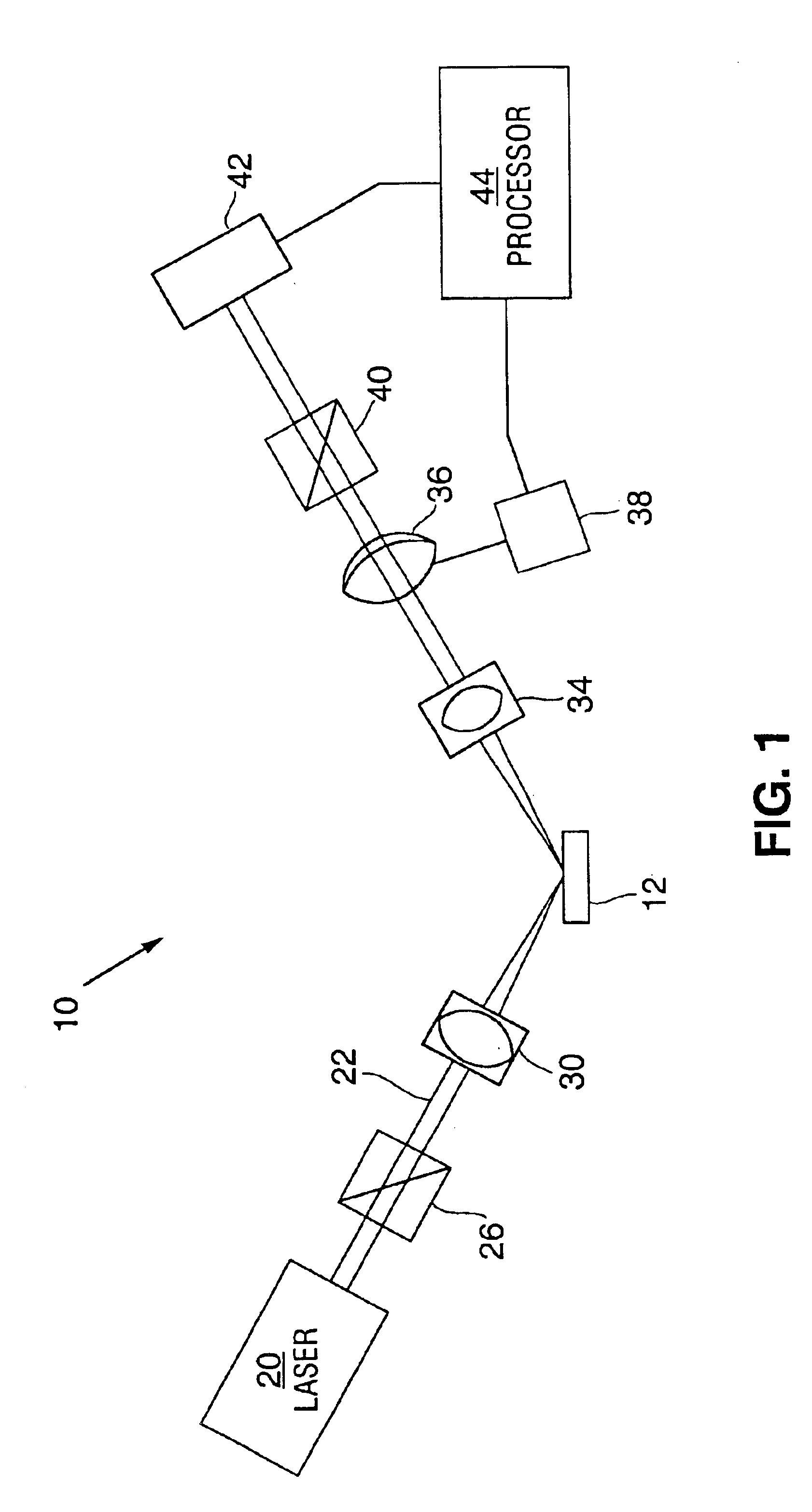
Referring to FIG. 1, there is illustrated an ellipsometer 10 constructed in accordance with the subject invention The ellipsometer includes a light source 20 for generating a probe beam 22 of light. In the preferred embodiment, light source 20 is a laser generating a wavelength stable probe beam. One example of such a laser is a helium-neon laser generating a probe beam having a wavelength of 633 nm.
The helium neon laser generates a very stable output wavelength which does not vary over time (i.e. varies less than 1%). Other gas discharge laser systems could be used. It would also be possible to use diode lasers since they generate a relatively coherent beam of light. At the present time, the wavelength output of diode lasers is less stable and effected by age and temperature and are therefore diode lasers are less desirable.
Beam 22 interacts with polarizer 26 to create a known polarization state. In the preferred embodiment, polarizer 26 is a linear polarizer made from a calcite prism, but in general, the polarization does not necessarily have to be linear, nor even complete. Polarizer 26 can also be made from magnesium fluoride. The azimuth angle of polarizer 26 is oriented so that the plane of the electric vector associated with the linearly polarized beam exiting from the polarizer 26 is at a known angle with respect to the plane of incidence (defined by the propagation direction of the beam 22 and the normal to the surface of sample 12). The azimuth angle is preferably selected to be on the order of 45 degrees because sensitivity is optimized when the reflected intensities of the P and S polarized components are approximately balanced. It should be noted that polarizer 26 can be omitted if the light source 20 emits light with the desired known polarization state.
The beam 22 is focused onto the sample 12 by lens assembly 30 at an oblique angle. Lens assembly 30 is discussed more fully below.
Light from probe beam 22 is reflected by the sample 12 symmetrically to the incident beam about the normal to the sample surface. The beam 22 is ideally incident on sample 12 at an angle on the order of 65 degrees to the normal of the sample surface because sensitivity to sample properties is maximized in the vicinity of the Brewster or pseudo-Brewster angle of a material.
Based upon well known ellipsometric principles, the reflected beam will generally have a mixed linear and circular polarization state after interacting with the sample, as compared to the linear polarization state of the incoming beam. Lens 34 collimates beam 22 after its reflection off of the sample 12.
The beam 22 then passes through a compensator (retarder) 36 which is rotated by electric motor 38. Compensator 36 introduces a relative phase delay δ (phase retardation) between a pair of mutually orthogonal polarized optical beam components. The amount of phase retardation is a function of the wavelength, the dispersion characteristics of the material used to form the compensator, and the thickness of the compensator.
Compensator 36 is rotated at an angular velocity ω (either continuously or in a step-wise fashion) about an axis substantially parallel to the propagation direction of beam 22. Compensator 36 can be any conventional wave-plate compensator, for example those made of crystal quartz. The thickness and material of the compensator 36 are selected such that a desired phase retardation of the beam is induced. In the preferred embodiment, compensator 36 is a zero-order plate formed from mica. Other types of compensators could be used including bi-plate compensators. Bi-plate compensators are constructed of two parallel plates of anisotropic (usually birefringent) material, such as quartz crystals of opposite handedness, where the fast axes of the two plates are perpendicular to each other and the thicknesses are nearly equal, differing only by enough to realize a net first-order retardation for the wavelength produced by the light source 20.
Beam 22 then interacts with polarizer 40, which serves to mix the polarization states incident on it. In this embodiment, polarizer 40 is a linear polarizer, preferably oriented at an azimuth angle of 90 degrees relative to the plane of incidence.
However, any optical device that serves to appropriately mix the incoming polarization states can be used as an analyzer. Polarizer 40 is preferably a prism formed from calcite.
It should be noted that the compensator 36 can be located either between the sample 12 and the polarizer 40 or between the sample 12 and the polarizer 26. It should also be noted that polarizers, lenses and compensator are all optimized in their construction for the specific wavelength of light produced by light source 20, which maximizes the accuracy of ellipsometer 10.
Beam 22 then strikes detector 42, which measures the intensity of the beam passing through the compensator/polarizer combination. The processor 44 processes the intensity information measured by the detector 42 to determine the polarization state of the light after interacting with the polarizer 40, and therefore the ellipsometric parameters of the sample. This information processing includes measuring beam intensity as a function of the azimuth (rotational) angle of the compensator about its axis of rotation. This measurement of intensity as a function of compensator rotational angle is effectively a measurement of the intensity of beam 22 as a function of time, since the compensator angular velocity is usually known and a constant.
For the purposes of this specification, the term analyzer is used generally to refer to those optical components necessary to determine the change in polarization state of the beam. These components may vary depending upon the type of ellipsometer configuration selected. The ellipsometer 10 of the present invention is not limited to the specific rotating compensator ellipsometer configuration discussed above. The scope of the present invention includes any ellipsometer configuration in conjunction with the light source 20 that measures the polarization state of the beam after interaction with the sample. For example, another ellipsometric configuration is to rotate either polarizer 26 or 40 with motor 38, instead of rotating the compensator 36.
In addition, null ellipsometry can also be employed. In a null ellipsometer, which can use the same elements as ellipsometer 10, information is derived by aligning the azimuthal angles of these elements until a null or minimum level intensity is measured by the detector 42. In the preferred null ellipsometry embodiment, compensator 36 is aligned so that its fast axis is at an azimuthal angle of 45 degrees relative to the plane of incidence of the sample 12. Polarizers 26 and 40 are rotated about beam 22 such that the light is completely extinguished (minimized) by the analyzer 36.
It is also conceivable to omit compensator 36 from ellipsometer 10, and use motor 38 to rotate either polarizer. The detector signal can be used to accurately measure the linear polarization component of the reflected beam. Then, the circularly polarized component is inferred by assuming that the beam is totally polarized, and what is not linearly polarized must be circularly polarized. Such an ellipsometer, commonly called a rotating-polarizer or rotating-analyzer ellipsometer, is termed “an incomplete” polarimeter, because it is insensitive to the handedness of the circularly polarized component and exhibits poor performance when the light being analyzed is either nearly completely linearly polarized or possesses a depolarized component.
In still another variant, a second compensator can be added, where the first compensator is located between the sample and the polarizer 40, and the second compensator located between the sample and the light source 20. These compensators could be static or rotating. An example of a single wavelength ellipsometer with a pair of rotating compensators is described in U.S. Pat. No. 5,798,837, cited above. Another example is disclosed in WO 00/65331 also incorporated herein by reference.
In any of these embodiments, to provide a static or varying retardation between the polarization states, the compensator can be replaced by a non-rotating opto-electronic element or photo-elastic element, such as a piezo-electric cell retarder which are commonly used in the art to induce a sinusoidal or static phase retardation by applying a varying or static voltage to the cell.
Lens Assembly
The ellipsometer 10 of the subject invention can be configured to focus the probe beam 22 to a smaller spot size than was previously attainable. As noted above, in the assignee's commercial version of the single wavelength ellipsometer, a spot size having dimensions on the order of 20×40 microns could be achieved. In order to reduce that spot size in the longer dimension to below 25 microns and preferably below 20 microns, a lens with a larger numerical aperture and a shorter focal length was necessary. Further, in order to reduce spherical aberrations, a lens was selected which was formed from a material wherein the index of refraction varies along the optical axis thereof.
As noted above, one such type of lens is manufactured by LightPath Technologies of New Mexico under the trademark Gradium® lenses. According to the manufacturer, a number of different glasses with varying indices of refraction are layered together. The glasses are melted to blend the materials continuously across the optical path. It is believed that this process is described in U.S. Pat. No. 5,992,179. Further information about these type of lenses can be obtained from the manufacturer's website at www.light.net (See “Products” and “Gradium lenses”).
While these materials have characteristics which permit a lens to be designed with a higher numerical aperture, a shorter focal length and with a minimum of spherical aberrations, they were not considered as particularly suitable for use in highly sensitive ellipsometric applications. More specifically, one of the important criteria for any ellipsometric lens system is that it should not induce polarization changes that vary with changes in ambient conditions. Such variations can occur when a lens expands or contracts with respect to the fixed lens mounting structure. Such size variation create stresses in the lens. Stresses in the lens create birefringent effects which alter the polarization of the beam in a manner which can degrade measurement.
In the past, it was common to use fused silica for these lenses. One key attribute of fused silica is that its coefficient of thermal expansion is quite low, on the order of 6×10⁻⁷/K Even so, to reduce stress birefringence as much as possible, the assignee herein developed a relatively stress free lens mounting system. While this stress free mounting system reduced stress in a fused silica lens to an acceptable level, it was not believed that such a mounting system could provide similar insensitivity for a material with a coefficient of thermal expansion so much larger than fused silica. However, after testing, it appears that the subject mount, described below, is suitable for use even with these Gradium glasses.
In one experimental arrangement, lens 48 was formed from G23SFN material from LightPath. FIG. 2 illustrates the index of refraction profile of this material. The lens (FIG. 6) was cut from a blank and had a spherical front surface (light input side) 50 with a curvature of about 32 mm. The rear surface (light output side) 52 had a slight spherical curvature of about 254 mm. The lens 48 was 4.6 mm thick at its center. The glass material at the rear surface 52 had an index of refraction of about 1.73 and the glass material at the high point of the front surface 50 had an index of refraction of about 1.78. This lens has a focal length of 40 mm and a numerical aperture of 0.29. However, since the diameter of the probe beam is small, i.e. about 8 mm, the effective numerical aperture of the lens for this arrangement was 0.1.
In experiments, this lens was capable of creating a spot size having a 1/e2 diameters of 8×16 microns compared to the 20×40 microns for the prior lens. The spot diameter (in the longer axis) in which 99% of the beam energy fell was 26 microns compared with 64 microns in the prior art. Such a spot size can be used to accurately measure within a 50×50 micron pad size.
Although not required, the lens in lens assembly 34 can also be formed from the Gradium glass material.
FIG. 3 is a graph of measurements taken when the beam spot was scanned across a boundary between an oxide having a 20 Å thickness to an oxide having a 500 Å thickness. Curve B illustrates data taken with the conventional fused silica lens having an NA of 0.35. Curve A illustrates data taken with the Gradium lens described herein. As can be seen, the transition between the boundary is much sharper using the lens of the subject invention.
FIG. 4 is a graph of measurements taken when the beam spot was scanned across a 50 micron wide thin oxide well. Once again, it can be seen from curve A1 that the edges of the well are more crisply defined with the Gradium lens than when a conventional fused silica lens (curve B1) was used.
FIGS. 5 and 6 illustrate the mirror mount 60 that was used with the subject Gradium index lens. An important aspect of this mirror mount is to provide a plurality of resilient O-rings to support the lens.
The mount 60 includes a front support 66 and a rear support 64. Lens 48 is mounted between the front and rear supports. The mount further includes an intermediate support 70 which helps support the radially outer edge of lens 48. Rear and intermediate supports are threaded to allow for assembly.
A first O-ring 74 is provided between the front support 66 and the front of the lens. A second O-ring 76 is provided between the intermediate support 70 and the radially outer edge of the lens. While the lens mount may be implemented with only these two O-rings, it is preferable to have three O-rings. In the preferred embodiment, an additional O-ring 78 is located between the rear support 64 and the rear of the lens.
Each of the O-rings is preferably formed from Viton and have an elasticity (Young's modulus) of 2.5×10⁶ N/m2. The thermal coefficient of expansion of this material is 160×106/K.
In summary, there has been provided an improved small spot ellipsometer for evaluating a sample. The ellipsometer includes a light source for generating a narrow bandwidth probe beam. An analyzer is provided for determining the change in polarization state of the beam after interaction with the sample. A lens is provided having a numerical aperture and focal length sufficient to focus the beam to a diameter of less than 20 microns on the sample surface. The lens is formed from a graded index glass wherein the index of refraction varies along its optical axis. The lens is held in a relatively stress free mount to reduce stress birefringence created in the lens due to changes in ambient temperature. The ellipsometer is capable of measuring features on semiconductors having a dimensions as small as 50×50 microns.

PUM

no PUM

Description & Claims & Application Information

We can also present the details of the Description, Claims and Application information to help users get a comprehensive understanding of the technical details of the patent, such as background art, summary of invention, brief description of drawings, description of embodiments, and other original content. On the other hand, users can also determine the specific scope of protection of the technology through the list of claims; as well as understand the changes in the life cycle of the technology with the presentation of the patent timeline. Login to view more.

Similar technology patents

Optimization method of N (N is greater than or equal to 20) primary color spectrum fitting target spectrum

ActiveCN111854951AExtended screening timeReduce accuracyMaterial analysis by optical meansSpectrum generationComputational physicsColor rendering index
Owner:FUDAN UNIV

Classification and recommendation of technical efficacy words

  • High coefficient
  • Reduce accuracy

Method and apparatus for producing carbon dioxide

InactiveUS6537514B1High coefficientIncrease mass flowNitrogen purification/separationCarbon compoundsIonCarbon dioxide
Owner:PRAXAIR TECH INC

Miniature quantum well thermoelectric device

InactiveUS20080257395A1High coefficientConversion efficiency be highThermoelectric device with peltier/seeback effectThermoelectric device junction materialsPhysicsElectric generator
Owner:HI Z

GPS position-finding system and method of finding position of GPS terminal

InactiveUS20050116858A1Reduce accuracyControl with pedestrian guidance indicatorPosition fixationTerrainSatellite
Owner:NEC CORP

Rotating electrical machine

InactiveUS20100102681A1Reduce accuracyIncrease axial dimensionDC commutatorStructural associationStatorEngineering
Owner:AISIN AW CO LTD
Why Eureka
Try Eureka