
Method and apparatus for predictably switching diversity antennas on signal dropout

a diversity antenna and signal dropout technology, applied in the field of can solve the problems of incomplete audio loss, complex prior art diversity antenna switching systems, and inability to predictably switch diversity antennas, so as to reduce the attenuation of rf signals, and avoid the effect of audio output noise spikes

Inactive Publication Date: 2005-03-22
SHURE INC (US)
View PDF9 Cites 29 Cited by
  • Summary
  • Abstract
  • Description
  • Claims
  • Application Information

AI Technical Summary

Benefits of technology

Using PIN diodes as variable RF signal attenuators, in series between each of the antennas of a diversity antenna system and the radio receiver input in a wireless microphone system, the strongest signal received from a transmitter can be seamlessly selected at the receiver without producing noise spikes caused by phase differences between the antennas. The PIN diode will conduct radio frequency energy when biased in the forward direction. By gradually biasing a PIN diode to conduct in a forward direction, its attenuation of a RF signal can be gradually increased and decreased. In a diversity antenna system, a PIN diode connected in series between the antenna and the receiver input, can be gradually forward biased, thereby gradually reducing the attenuation of RF signals passing through the diode from the antenna to the input. Simultaneously, another PIN diode connected in series with another antenna and coupled to the receiver input, can be gradually reversed biased so as to gradually attenuate signal from the other antenna.
By gradually modulating the bias current of PIN diodes, they can be used to progressively attenuate and de-attenuate signals from two or more diversity antennas that are coupled to a common summing node that is coupled to the input of the radio receiver. Signals received by one antenna can be seamlessly combined with signals from another antenna so as to avoid sudden phase shifts that can produce unacceptable audio output noise spikes.
PIN diodes are small, inexpensive and easily controlled to modulate their RF attenuation level.

Problems solved by technology

As a wireless microphone is moved about a room, multi-path signals can adversely affect the demodulated audio output from the receiver because multi-path signals will produce phase anomalies in the reception process that sound like popping noise or may even cause complete audio loss.
At least one problem with a diversity antenna system is switching the appropriate antenna to the receiver in such a way so as to seamlessly couple the receiver to the proper antenna.
When high fidelity audio reproduction is required in a small size package and at the lowest possible cost, prior art diversity antenna switching system are too complex, too large, or too expensive.
Prior art low cost, switching systems also suffer from audio switch noise spikes that they produce in the receiver when they perform a hard instantaneous switch over from one antenna to another.

Method used


Image

  • Method and apparatus for predictably switching diversity antennas on signal dropout
  • Method and apparatus for predictably switching diversity antennas on signal dropout
  • Method and apparatus for predictably switching diversity antennas on signal dropout

Examples


Embodiment Construction

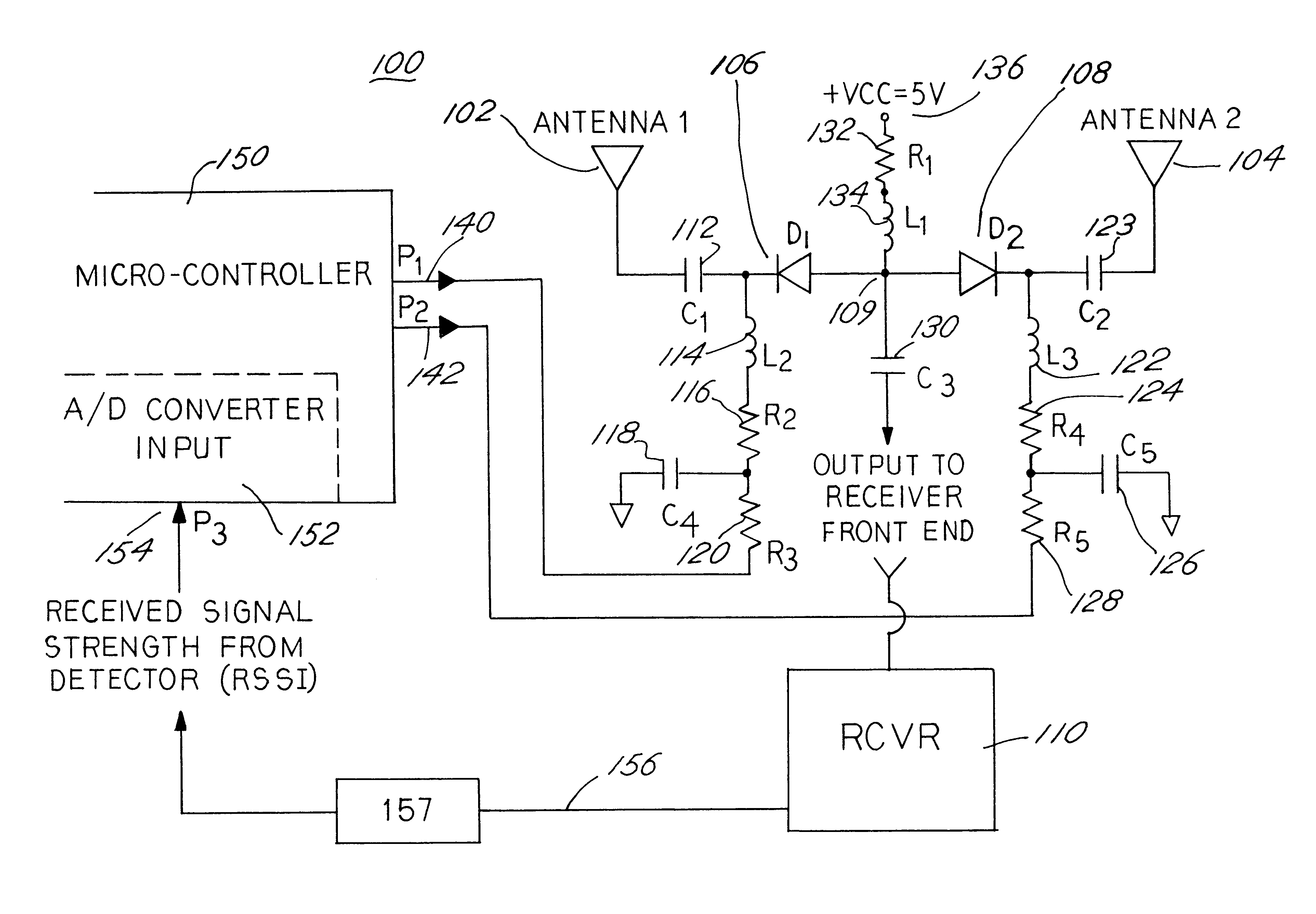
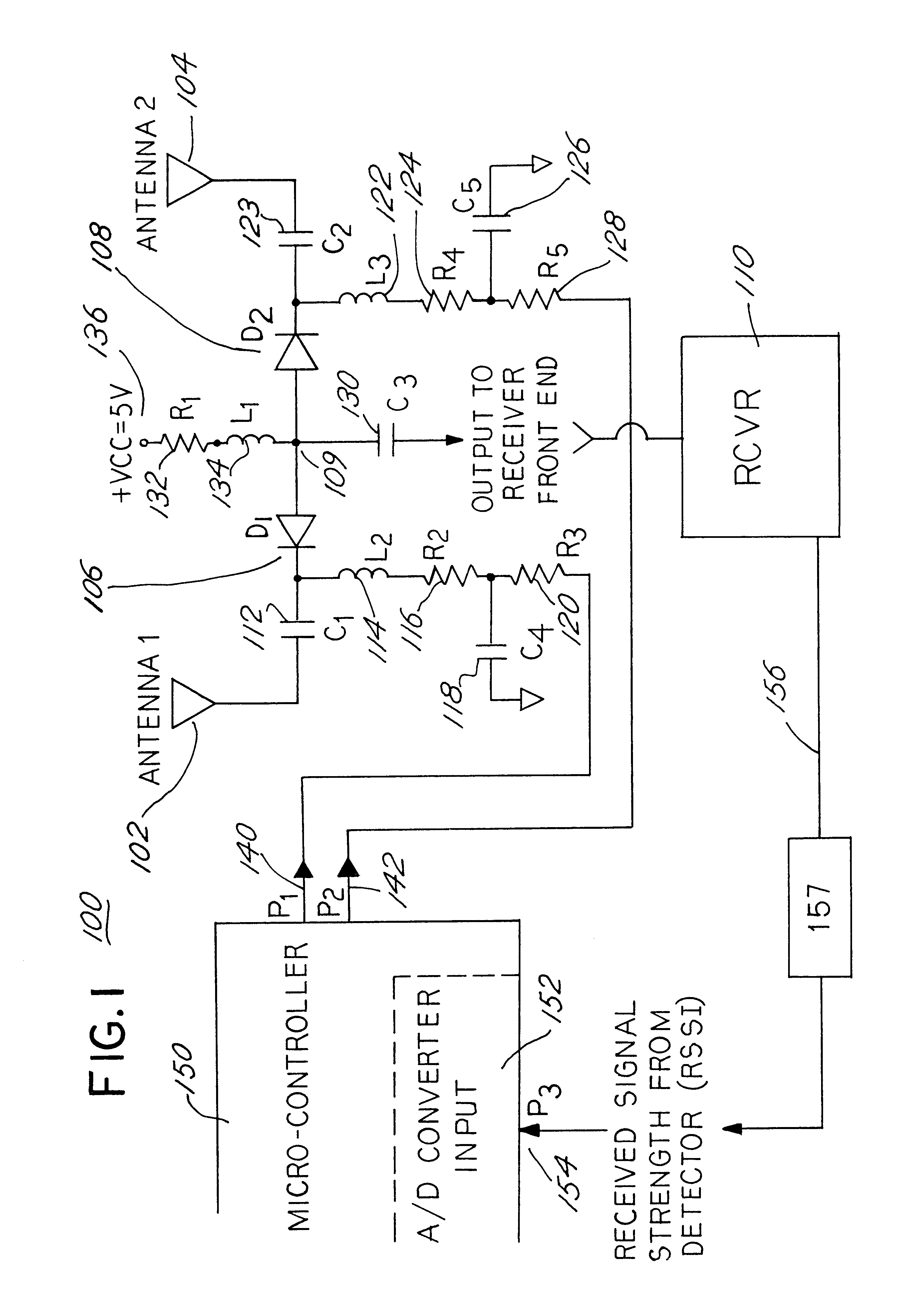
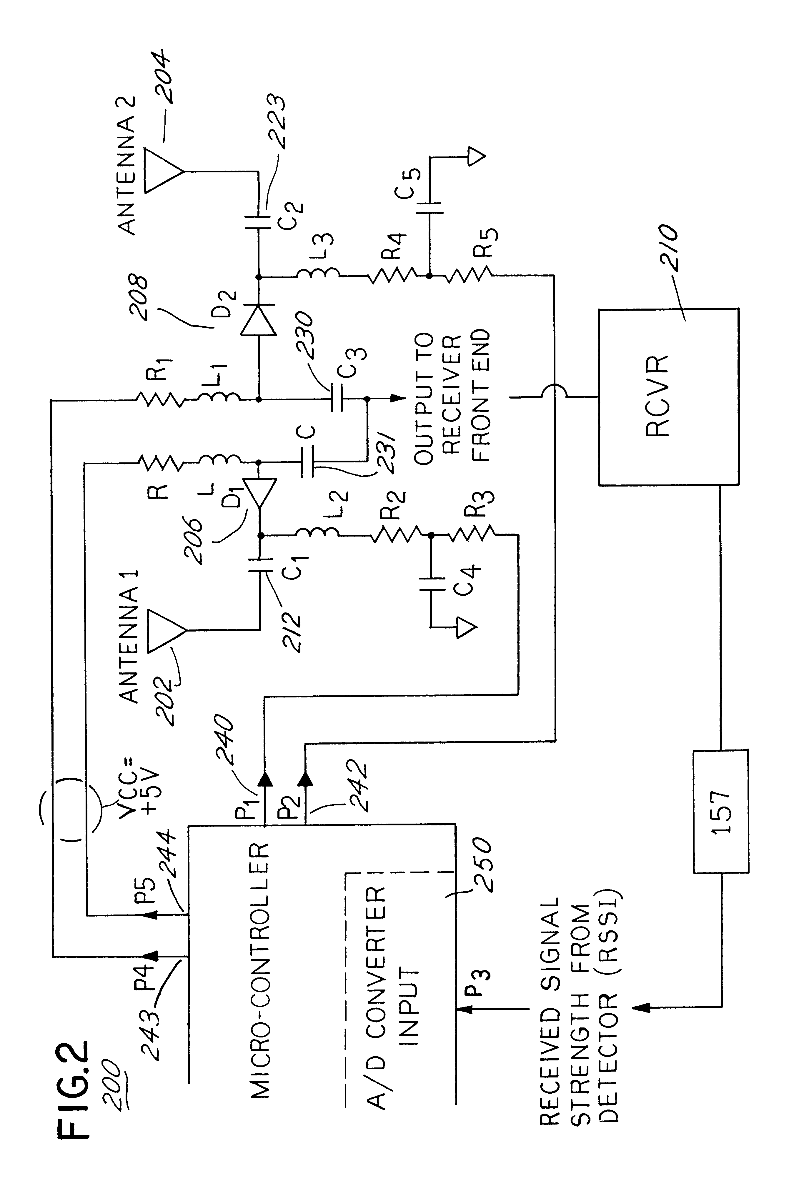
FIG. 1 shows a schematic diagram of the preferred embodiment of diversity receiving apparatus for coupling radio frequency signals from at least one antenna of a pair of such antennas into a radio receiver for demodulation. The diversity receiving apparatus 100 is comprised two radio antennas 102 and 104 for detecting signals radiated from a transmitter not shown. While the antennas 102 and 104 are only shown schematically in FIG. 1, for improving signal reception, the actual antennas are preferably spaced as far apart as practical.

The first antenna 102 is capacitively coupled 112 to the cathode of a first PIN diode 106. The anode of the first PIN diode 106 is connected to a summing node 109 that is capacitively coupled 130 to the input of a radio frequency receiver 110 which demodulates radio frequency signals picked up at antenna 102 and outputs an audio frequency signal. The second antenna 104 is also capacitively coupled 123 to the cathode of a second PIN diode 108, the anode of...


PUM


Abstract

A low-cost diversity antenna switching system and method is realized by controlling bias voltages on PIN diodes. By increasing the reverse bias voltage impressed upon a PIN diode, an RF signal impressed upon the diode is increasingly attenuated. As the PIN diode is forward biased to conduct in the forward direction, RF attenuation decreases. Two or more PIN diodes are used to increasingly attenuate signals from one antenna as attenuation of signals from another antenna is gradually decreased. The progression of the bias voltages is accomplished using a microprocessor that monitors a received signal strength indicator (RSSI) signal from a radio receiver. The RSSI is used to control which of two antennas are coupled into the receiver by predicting a signal fade.

Description

FIELD OF THE INVENTIONThis invention relates to diversity antenna switching systems. In particular, this invention relates to a low cost, diversity antenna switching system for use with high fidelity audio equipment.BACKGROUND OF THE INVENTIONDiversity receiving systems and diversity antennas are well known in the communications art. In general, diversity antenna systems are used to accommodate the RF signal fading and multi-path signal propagation anomalies that are common at VHF and UHF frequencies. Signal fading and multi-path signals can adversely effect reception of a radio frequency's signal and, by selectively choosing one of two or more spatially separated antennas that pick up a signal, fading and multi-path effects can be reduced. Multiple antennas are routinely used with cellular telephones and automobile radios.Multiple antennas are now also used with wireless microphone systems, which include a remote, low-power portable transmitter, the signals of which are received an...

Claims


Application Information

Patent Timeline
IPC IPC(8): H04B7/08
CPCH04B7/0802H04B7/0814H04B7/0831H04B7/00
Inventor KENKEL, MARK A.REIHL, EDGAR C.
Owner SHURE INC (US)
Learn More