Automatic calibration method for use in electronic compass

a technology of automatic calibration and electronic compass, which is applied in the direction of instruments, measurement devices, surveying and navigation, etc., can solve the problems of inability to perform calibration process, difficulty in calculating correct azimuth angle, and the inability of the calibration method to update the calibration data according to the changing peripheral environmental conditions, etc., to achieve the effect of quick response to environmental variations

Inactive Publication Date: 2005-03-29
SAMSUNG ELECTRO MECHANICS CO LTD
View PDF5 Cites 34 Cited by
  • Summary
  • Abstract
  • Description
  • Claims
  • Application Information

AI Technical Summary

Benefits of technology

It is another object of the present invention to provide an automatic calibration method for use in an electronic compass, which performs an automatic calibration process

Problems solved by technology

However, the conventional electronic compass has a disadvantage in that it must receive an entry signal from a user to carry out a desired calibration process, such that it cannot perform the calibration process without receiving the user's entry signal.
Therefore, provided that offset and amplitude values of the output signal of the electronic compass are unexpectedly changed in the case of carrying out the calibration process only using the user's entry signal, changed offset and amplitude values are real-time reflected in a resultant geomagnetic signal of the electronic compass, resulti

Method used


Image

  • Automatic calibration method for use in electronic compass
  • Automatic calibration method for use in electronic compass
  • Automatic calibration method for use in electronic compass

Examples


Embodiment Construction

Now, preferred embodiments in accordance with the present invention will be described in detail with reference to the accompanying drawings. In the drawings, the same or similar elements are denoted by the same reference numerals even though they are depicted in different drawings.

FIG. 4 is a block diagram illustrating a control module of an electronic compass in accordance with the present invention.

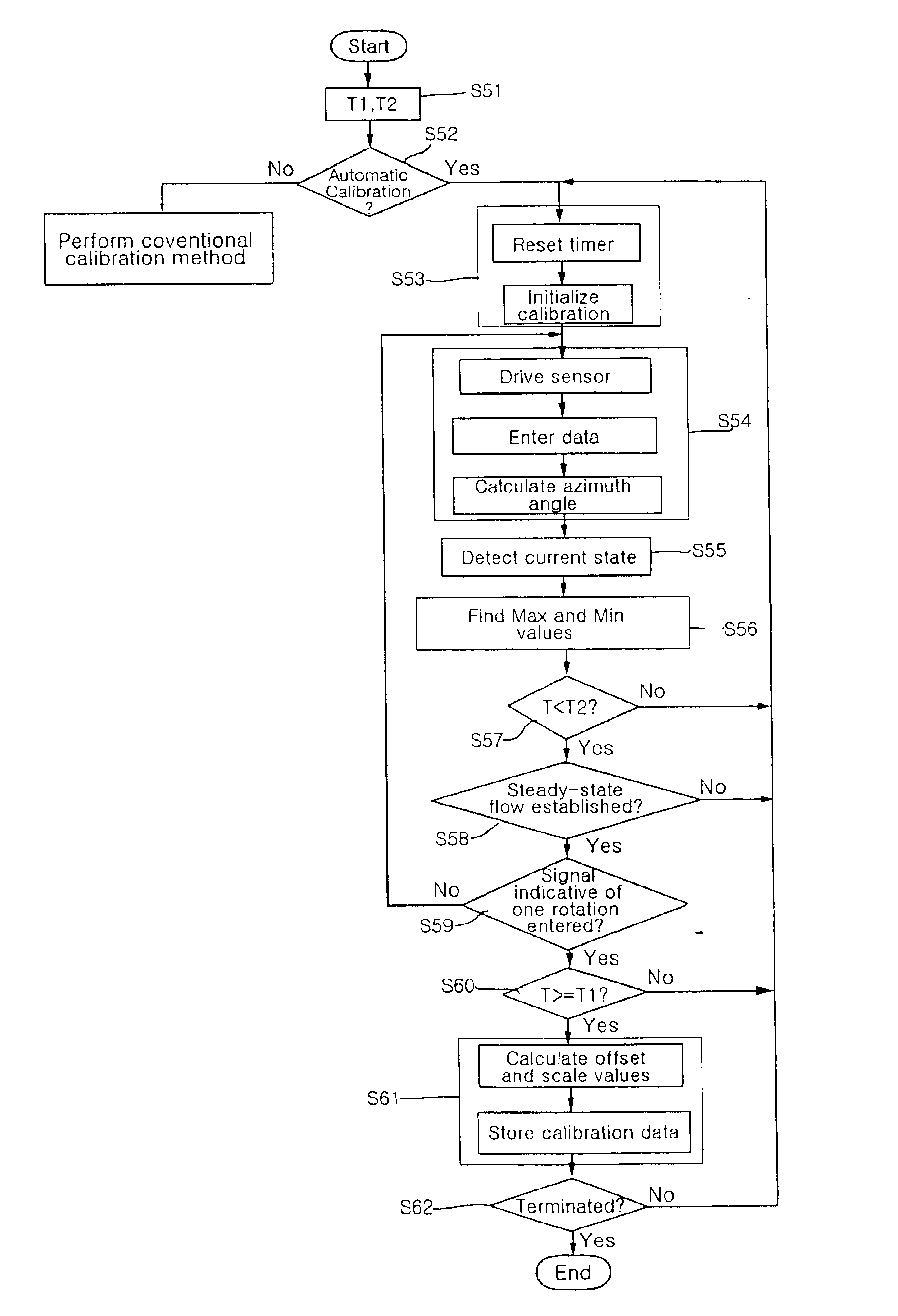
Referring to FIG. 4, the control module for use in the electronic compass pre-determines minimum and maximum calibration effective times T1 and T2 needed for a system containing the controller. The minimum calibration effective time T1 is a minimum time during which calibration data can be considered to be effective, and the maximum calibration effective time T2 is a maximum time during which calibration data can be considered to be effective. In order to carry out an effective calibration operation, a calibration duration time must be longer than the minimum calibration effective time ...


PUM


Abstract

An automatic calibration method for use in an electronic compass. Using the automatic calibration method, the electronic compass automatically calculates and corrects offset and scale values of a geomagnetic signal by detecting one rotation of a geomagnetic axis during a predetermined period of time. The electronic compass calculates an azimuth angle upon receiving geomagnetic data from the geomagnetic sensor, and finds maximum and minimum values of sensor signals of individual axes of the geomagnetic sensor using the received geomagnetic data such that it can correct or calibrate deviation of the azimuth angle. When a time consumed for calibration is the same or shorter than a maximum calibration effective time, the electronic compass determines whether a current state of the detected entry signal indicates a predetermined steady-state flow. If the current state indicates the steady-state flow, at the same time a signal indicative of one rotation of the geomagnetic sensor is received, and the time consumed for calibration is longer than a predetermined minimum calibration effective time, the electronic compass calculates offset and scale values using the maximum and minimum values and stores the calculated offset and scale values.

Description

BACKGROUND OF THE INVENTION1. Field of the InventionThe present invention relates to an automatic calibration method for use in an electronic compass, and more particularly to an automatic calibration method for use in an electronic compass, which automatically calculates and corrects offset and scale values of a geomagnetic signal by detecting one rotation of a geomagnetic axis during a predetermined period of time using a timer, performs automatic calibration capable of calculating offset and scale values of a geomagnetic signal without receiving additional entry data from a user, and quickly copes with environmental variation.2. Description of the Related ArtIn recent times, there have been developed small-sized and low-priced geomagnetic sensor modules and electronic compasses. With the increasing development of the MEMS (Micro-Electro Mechanical Systems) technology, chip-sized geomagnetic sensor modules have been newly developed and used for a variety of applications. There is ...

Claims


Application Information

Patent Timeline
IPC IPC(8): G01C17/00G01C17/38G01C17/32
CPCG01C17/38
Inventor KANG, JIN YONGCHOI, WON TAEKIM, CHANG HYUNJEONG, HA WOONGJO, HAN CHULKWON, OH JO
Owner SAMSUNG ELECTRO MECHANICS CO LTD
Why Eureka
Try Eureka