Enhanced cooling system

a cooling system and heat exchange technology, applied in the field of enhanced cooling systems, can solve problems such as system failur

Inactive Publication Date: 2005-03-29
CARRIER CORP
View PDF19 Cites 35 Cited by
  • Summary
  • Abstract
  • Description
  • Claims
  • Application Information

AI Technical Summary

Benefits of technology

It is an object of the invention to provide a system which will eliminate, when possible, the need to use a compressor within a refrigerant loop without relying on the positioning of the condenser relative to the evaporator.
It is another object of the invention to provide a system employing water in heat exchange relationship with refrigerant in a refrigerant loop that will eliminate the need to use a compressor under favorable outside temperature conditions.

Problems solved by technology

This system will not work in situations where the condenser unit and the evaporator unit cannot be so positioned relative to each other.

Method used


Image

  • Enhanced cooling system
  • Enhanced cooling system
  • Enhanced cooling system

Examples


Embodiment Construction

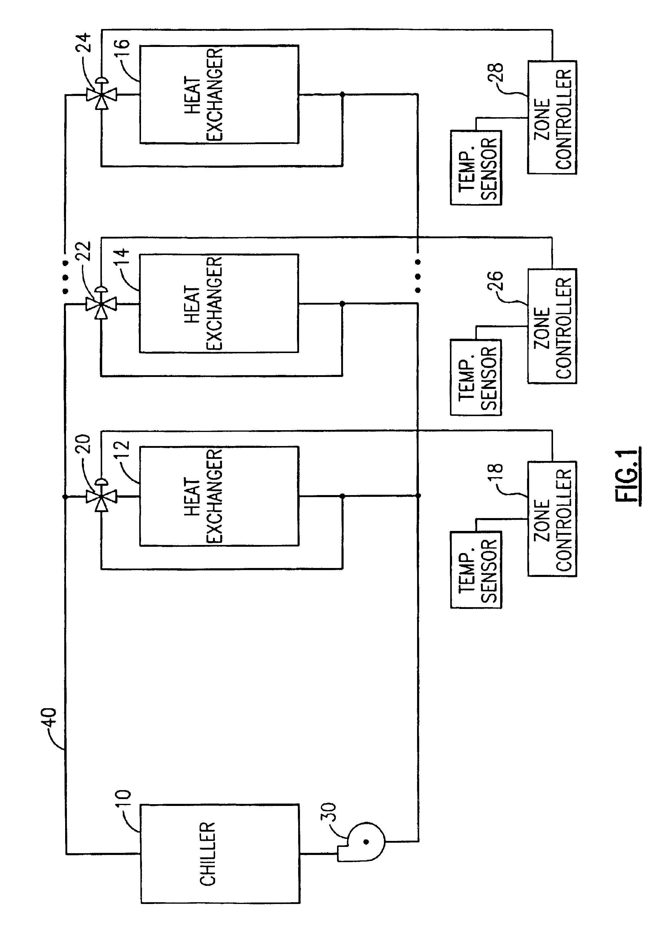
Referring to FIG. 1, a chiller 10 delivers chilled water to fan coil heat exchangers 12, 14 and 16. Water from the chiller 10 flows through the fan coil heat exchanger 12 in the event that a zone controller 18 authorizes such a flow by the positioning of a control valve 20. The zone controller 18 may also divert any water flow around the fan coil heat exchanger 12 by a further positioning of the control valve 20. It is to be appreciated that the fan coil heat exchangers 14 and 16 operate in a similar fashion in response to the positioning of control valves 22 and 24 under the control of zone controller 26 and 28. Each fan coil heat exchanger conditions air flowing through the fan coil heat exchanger. The resulting conditioned air is provided to spaces to be cooled. Each space is often referred to as a “zone of cooling”. It is finally to be noted that the water circulating through or around each fan coil heat exchanger is ultimately pumped back into the chiller 10 by a water pump 30 ...


PUM


Abstract

An air conditioning system is disclosed which takes advantage of low ambient temperature conditions so as to activate a refrigerant flow that bypasses the compressor. The activation of the refrigerant flow is achieved by the intelligent control of a pump positioned between the outlet of the condenser and the inlet of an expansion device upstream of the evaporator. The refrigerant flow produced by the pump does not require any particular positioning of the condenser and evaporator components with respect to each other. The evaporator preferably absorbs heat from water circulating in a secondary loop which is used to remove heat from a building by one or more fan coil units.

Description

BACKGROUND OF THE INVENTIONThis invention relates to the refrigerant heat exchange loop in systems which remove heat from one or more parts of a building that are to be cooled. In particular, this invention relates to the effective use of the refrigerant heat exchange loop in association with a water heat exchange loop in systems which employ water as a heat exchange medium to remove heat from various parts of a building.It is desirable that a system for cooling one or more parts of a building be as efficient as possible. This includes minimizing the consumption of energy by the various components of the system when performing their respective functions. Various approaches have been taken to achieve this goal. These include the use of energy efficient components that minimize the consumption of electricity while performing their particular functions within the system. Examples of such components include energy efficient motors which drive compressors and / or fans within the system. S...

Claims


Application Information

Patent Timeline
Patent Type & Authority Patents(United States)
IPC IPC(8): F25B41/00F25B25/00
CPCF25B25/00F25B41/00Y10S62/02F25B2400/0401
Inventor GRABON, MICHEL K.GIROD, XAVIERNIEVA, KENNETH J.RIGAL, PHILIPPE
Owner CARRIER CORP
Why Eureka
Try Eureka