
Integrating fluxgate for magnetostrictive torque sensors

a technology of magnetostrictive torque and fluxgate, which is applied in the field of sensing torque, can solve the problems of unfavorable reduction of the sensitivity of conventional magnetostrictive torque sensors, and achieve the effect of sufficient compactness

Inactive Publication Date: 2005-03-29
STEERING SOLUTIONS IP HLDG +1
View PDF108 Cites 22 Cited by
  • Summary
  • Abstract
  • Description
  • Claims
  • Application Information

AI Technical Summary

Benefits of technology

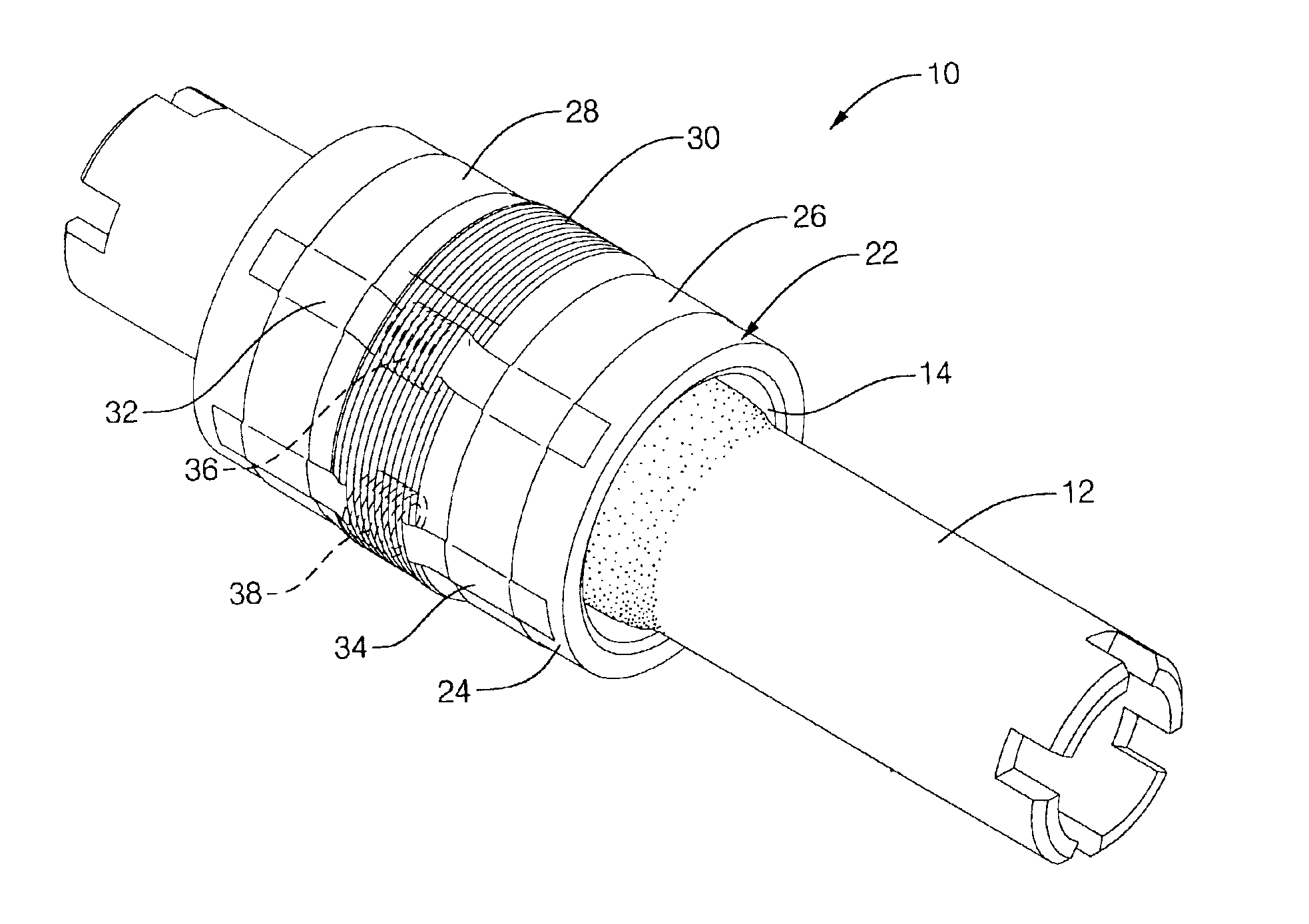
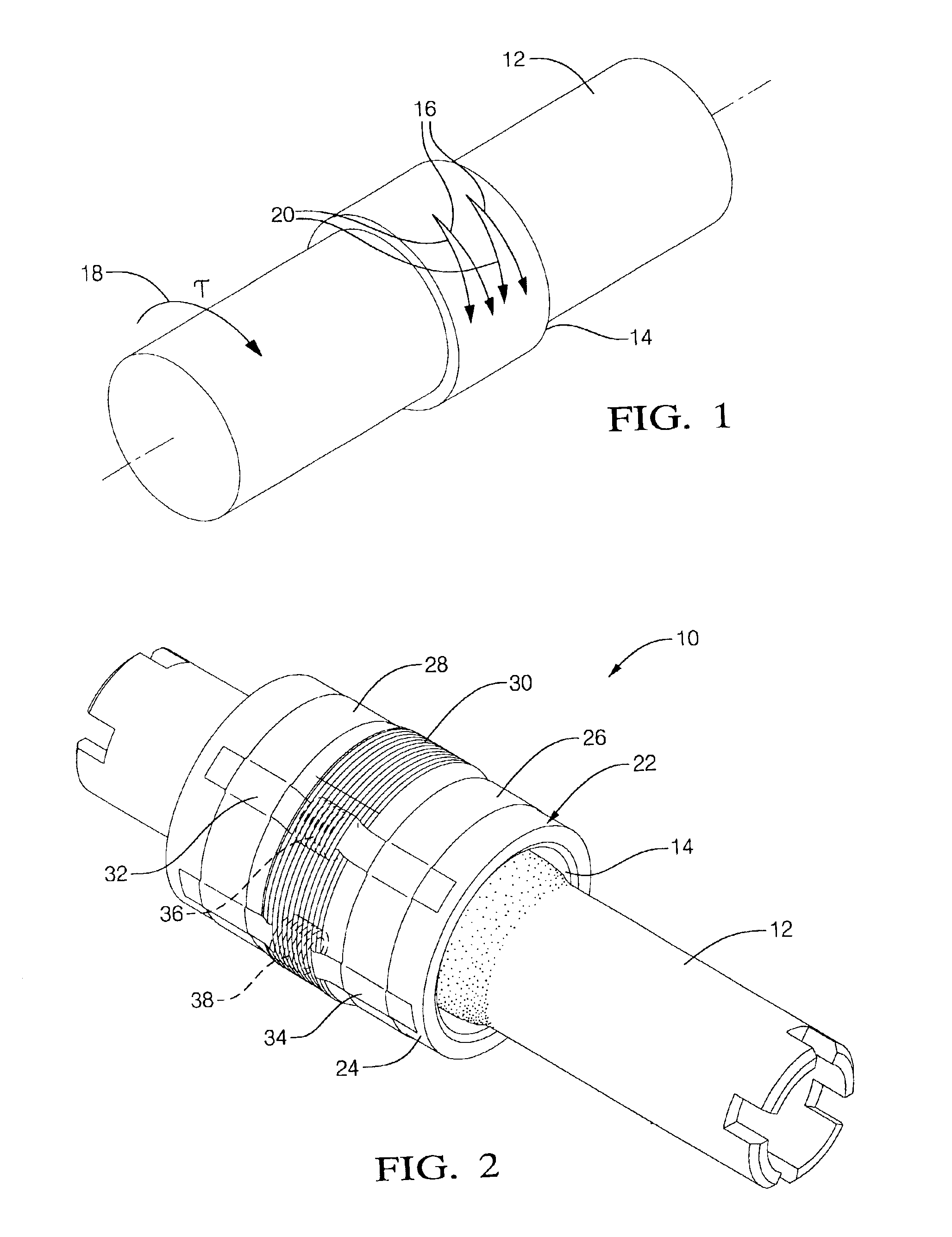
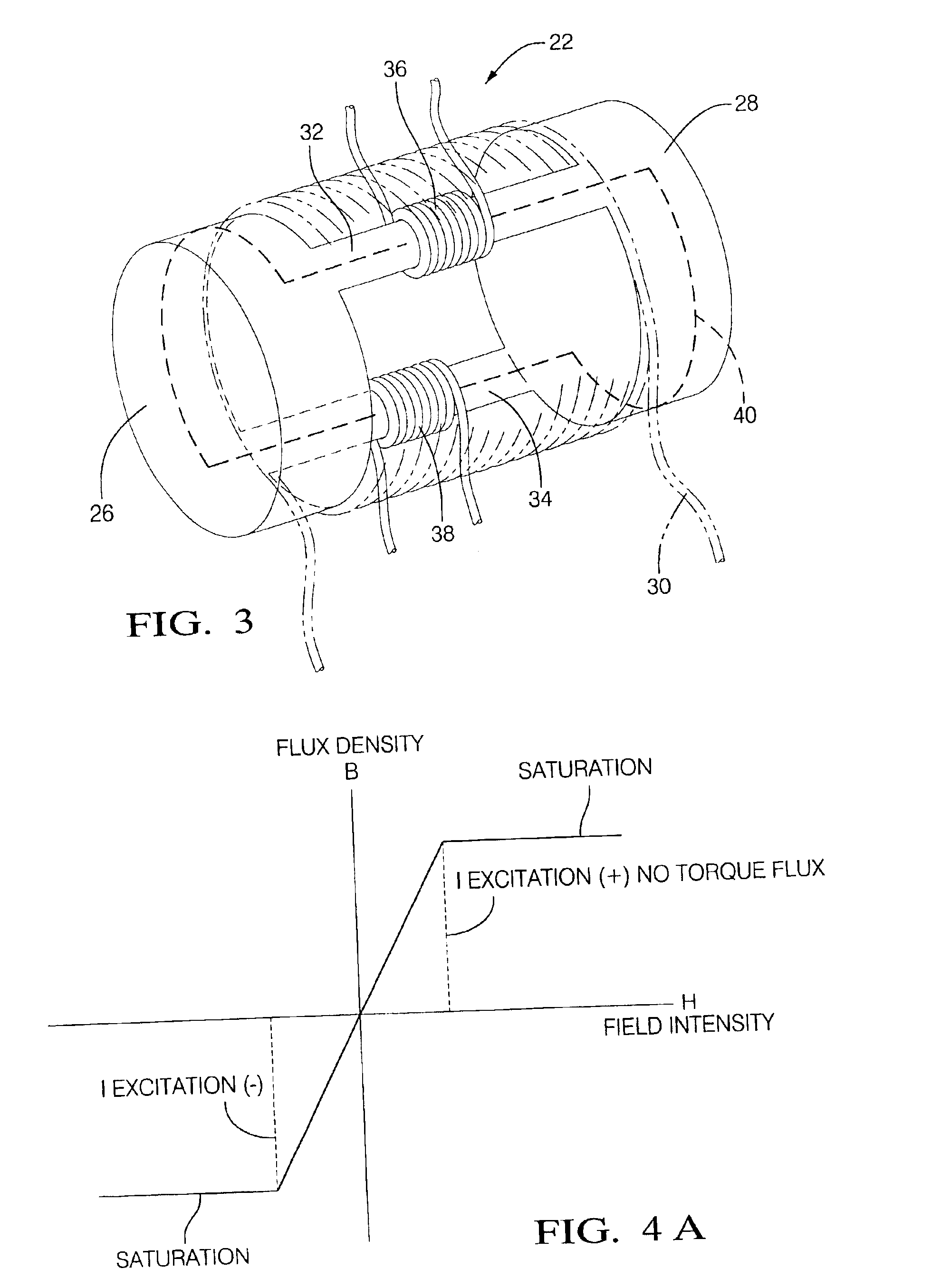
The present invention provides a torque sensor that is compact and can be used in space-limited applications such as automotive applications. The torque sensor includes a magnetostrictive material, a fluxgate return strip, and an excitation coil. The fluxgate return strips are connected to the integrating rings, which pick up flux signals along the entire periphery of the magnetostrictive material. The sensor measures the applied torque to the shaft by using a null detection scheme on the low reluctance closed loop flux path. The technical effect of the invention is to provide a compact and efficient torque sensor for accurate measurement of applied torque.

Problems solved by technology

As understood herein, the air gap, heretofore necessary to permit relative motion between the shaft and sensor, nonetheless undesirably reduces the sensitivity of conventional magnetostrictive torque sensors.

Method used


Image

  • Integrating fluxgate for magnetostrictive torque sensors
  • Integrating fluxgate for magnetostrictive torque sensors
  • Integrating fluxgate for magnetostrictive torque sensors

Examples


Embodiment Construction

Referring now to FIGS. 1-18 exemplary embodiments of a torque sensing apparatus 10 are illustrated. In an exemplary embodiment and referring in particular to FIG. 1, the torque-subjected member is in the form of a cylindrical shaft 12. However, the present disclosure is not intended to be limited to the specific configurations illustrated in FIG. 1. The shaft comprises a non-magnetic material, such as a stainless steel or aluminum. Disposed on the surface of shaft 12 is a magnetostrictive material 14. The magnetostrictive material is coated on or applied to the shaft in a manner that will produce a flux signal when the torque is applied to the shaft. The same signal is collected by the integrating fluxgate for measuring the torque applied to the shaft. An example of the magnetostrictive material is of the type disclosed in U.S. Pat. No. 6,645,039, the contents of which are incorporated herein by reference thereto. Of course, other types of magnetostrictive materials are contemplated...


PUM

PropertyMeasurementUnit
frequencyaaaaaaaaaa
AC voltageaaaaaaaaaa
frequencyaaaaaaaaaa

Abstract

A torque sensing apparatus for picking up a magnetic field of a magnetostrictive material disposed on a shaft, the torque sensing apparatus having: a first integrating ring; a second integrating ring; a first fluxgate return strip and a second fluxgate return strip each being connected to the first integrating ring at one end and the second integrating ring at the other end; an excitation coil; and a feedback coil; wherein the first integrating ring and the second integrating ring are configured to be positioned to pick up flux signals along the entire periphery of the ends of the magnetostrictive material.

Description

TECHNICAL FIELDThis disclosure relates to torque sensing apparatus and, in particular, an apparatus and method for sensing the torque applied to a rotating shaft.BACKGROUNDIn systems having rotating drive shafts it is sometimes necessary to know the torque and speed of these shafts in order to control the same or other devices associated with the rotatable shafts. Accordingly, it is desirable to sense and measure the torque applied to these items in an accurate, reliable and inexpensive manner.Sensors to measure the torque imposed on rotating shafts, such as but not limited to shafts in vehicles, are used in many applications. For example, it might be desirable to measure the torque on rotating shafts in a vehicle's transmission, or in a vehicle's engine (e.g., the crankshaft), or in a vehicle's automatic braking system (ABS) for a variety of purposes known in the art.One application of this type of torque measurement is in electric power steering systems wherein an electric motor i...

Claims


Application Information

Patent Timeline
Patent Type & Authority Patents(United States)
IPC IPC(8): G01L3/02G01L3/10
CPCG01L3/105G01L3/102
Inventor NAIDU, MALAKONDAIAHHEREMANS, JOSEPH PIERRENEHL, THOMAS WOLFGANGSMITH, JOHN R.FULLER, BRIAN K
Owner STEERING SOLUTIONS IP HLDG
Learn More