Strapping machine with self cleaning feed limit switch components

a technology of feed limit switch and component, which is applied in the direction of bundling machine details, paper/cardboard containers, manufacturing tools, etc., can solve the problems of equipment operation, control and switching, monitoring and maintenance, and equipment operation may be less than optimal in the environment in which strapping machines opera

Inactive Publication Date: 2005-03-29
SIGNODE IND GRP
View PDF3 Cites 8 Cited by
  • Summary
  • Abstract
  • Description
  • Claims
  • Application Information

AI Technical Summary

Benefits of technology

The strapping machine includes a limit switch assembly that limits the introduction of contaminants to the switch components. The switch assembly prevents the accumulation of dust and debris in the pockets formed by the sliding switch components and is self cleaning in that it clears dust and debris during normal switch operation.
The sliding element is movable between a strap not present position when the second course of strapping material is not present at the limit switch, and a strap present position when the second course of strapping material is present at the limit switch. Contact of the second course of strapping material with the internal portion lip urges the limit switch from the strap not present position to the strap present position. Movement of the sliding element between the strap present and strap not present positions urges the sliding element inclined surfaces to dislodge debris that is present in the strapping head internal and external channels.

Problems solved by technology

It will, however, be recognized that the environment in which strapping machines operate may be less than optimal vis-a-vis equipment operation, instrumentation, control and switching.
This is due in large part to the dust and debris that is associated with the goods being strapped, as well as the strapping material itself.
While these efforts have met with some success in limiting the ingress of contamination, they nevertheless require monitoring and maintenance to assure proper operation.

Method used


Image

  • Strapping machine with self cleaning feed limit switch components
  • Strapping machine with self cleaning feed limit switch components
  • Strapping machine with self cleaning feed limit switch components

Examples


Embodiment Construction

While the present invention is susceptible of embodiment in various forms, there is shown in the drawings and will hereinafter be described a presently preferred embodiment with the understanding that the present disclosure is to be considered an exemplification of the invention and is not intended to limit the invention to the specific embodiment illustrated.

It should be further understood that the title of this section of this specification, namely, “Detailed Description Of The Invention”, relates to a requirement of the United States Patent Office, and does not imply, nor should be inferred to limit the subject matter disclosed herein.

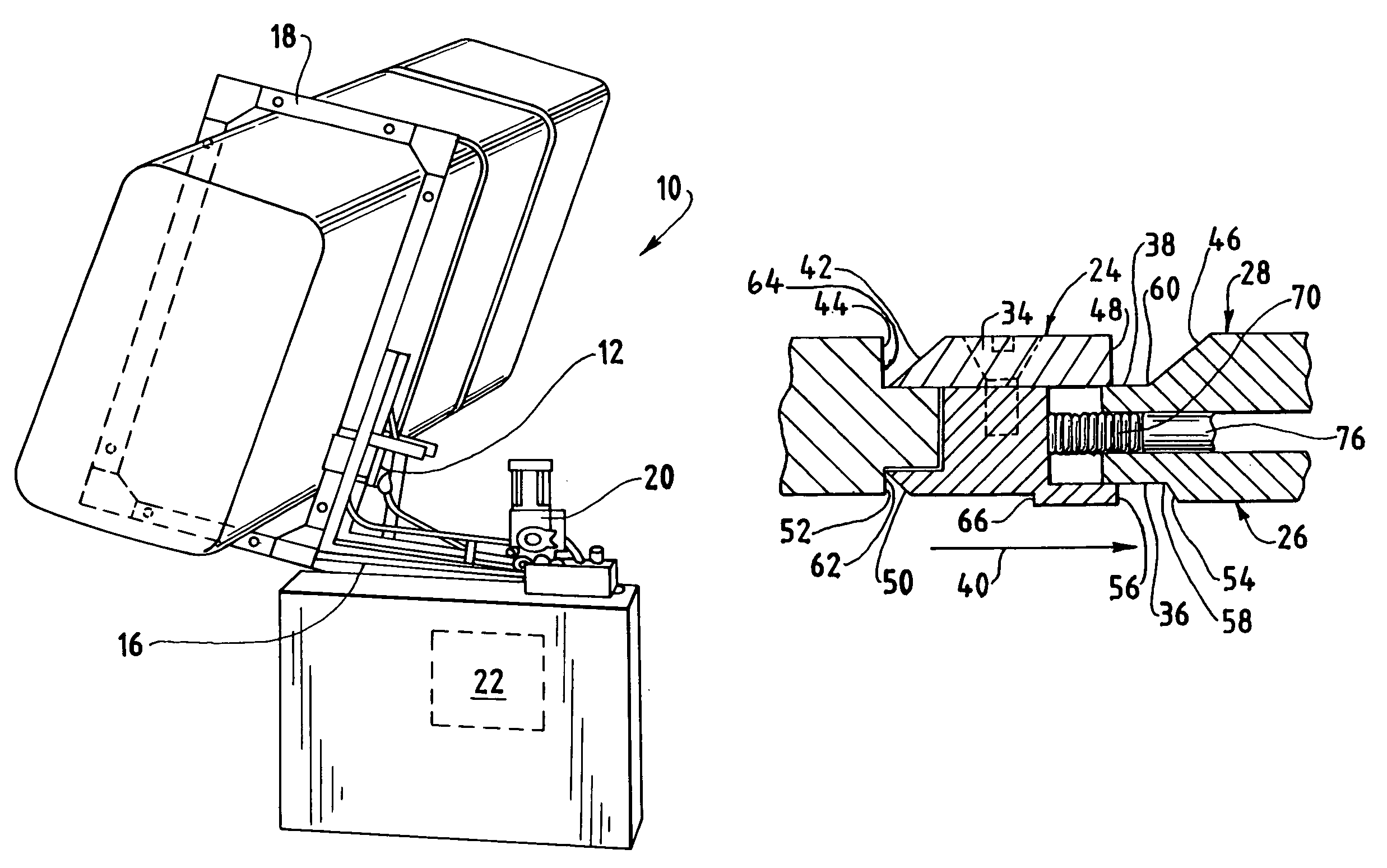
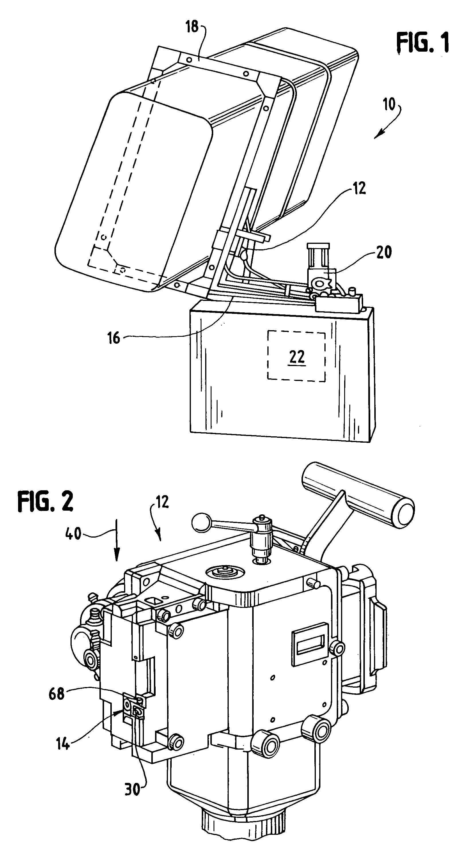
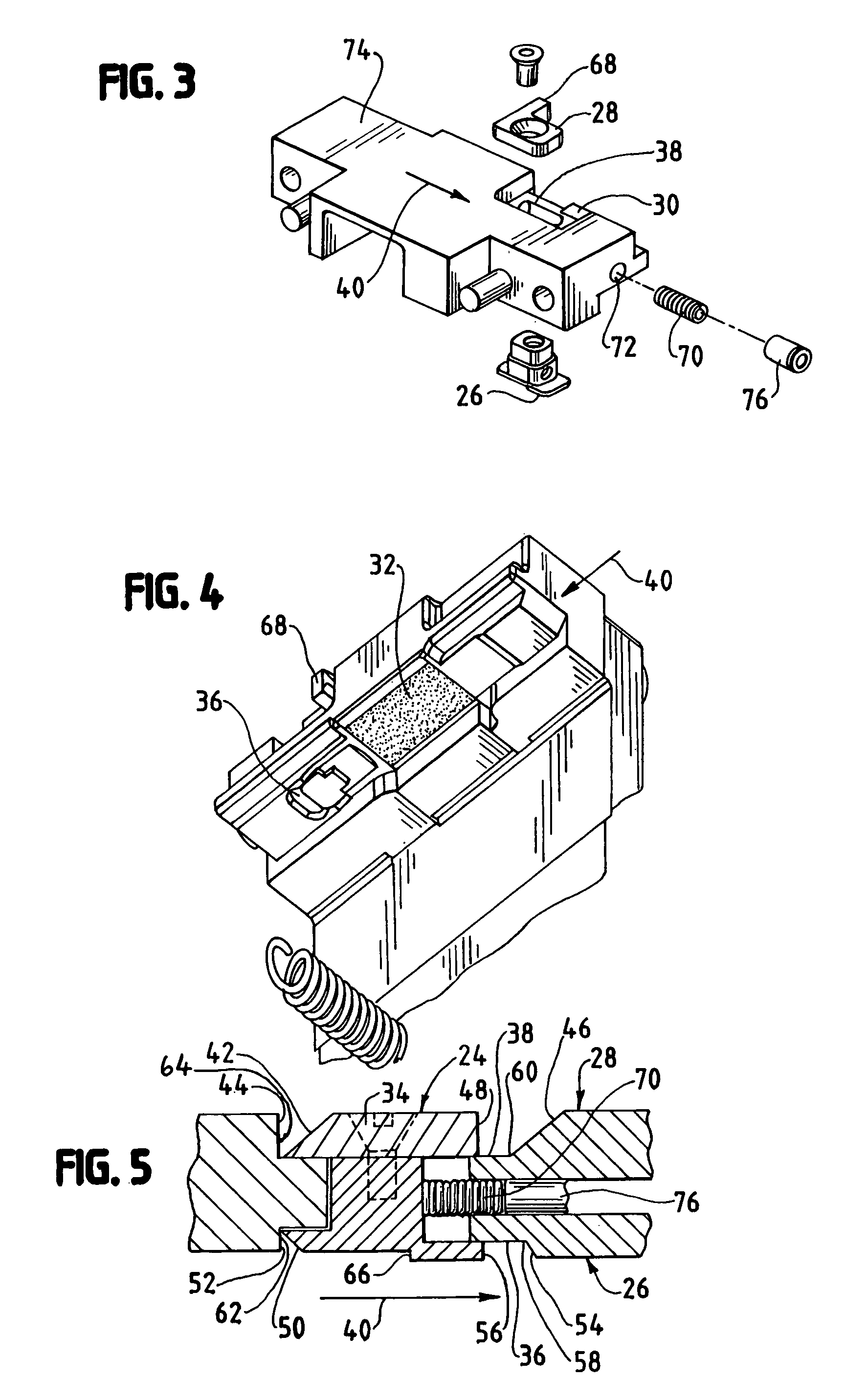
Referring to the figures and in particular FIG. 1, there is shown a strapping machine 10 having a strapping head 12 with a self cleaning feed limit switch 14. The strapping machine 10 includes, generally, a frame 16, a strap chute 18, a feed assembly 20 and the strapping head 12. A controller 22 provides automatic operation and control of the stra...


PUM


Abstract

A self-cleaning limit switch is for use in a strapping machine of the type configured to convey strapping material around a load, receive first and second courses of the strapping material, position, tension and seal the strapping material around a load. The strapping machine includes a strapping head having internal and external limit switch channels formed therein. The limit switch includes a sliding element having internal and external sliding portions rigidly connected to one another. The internal sliding portion is positioned in the strapping head internal limit switch channel and the external portion is positioned in the strapping head external limit switch channel. The internal and external sliding portions include an inclined surface at a rearward end thereof and upstanding walls at a forward end thereof. The internal sliding portion has a lip for engaging the second course of strapping material. The external sliding portion includes a position indicating element thereon. The sliding element is movable between a strap not present position when the second course of strapping material is not present at the limit switch, and a strap present position when the second course of strapping material is present at the limit switch. Movement of the sliding portions dislodges debris that is present in the strapping head internal and external channels. A strapping machine having a strapping head with the self cleaning limit switch is also disclosed.

Description

BACKGROUND OF THE INVENTION The present invention is directed to an improved feed limit switch configuration for a strapping machine. More particularly, the present invention is directed to feed limit switch configurations for a strapping machine that, by action of the switches, eliminated dust and debris from the switches. Strapping machines are used for securing straps around loads. Known strappers include a strapping head and drive mechanism mounted within a frame. Strapping material is fed from a supply (e.g., a dispenser) into a chute that is mounted to the frame. A typical drive mechanism includes feed wheels that “push” the material through the chute via the strapping head. The leading end of the strapping material traverses the chute and re-enters the strapping head at the end of the chute. A number of functions are carried out within the strapping head. First, the strapping material that “reenters” the chute is gripped by a gripper when the strap reaches and contacts a limi...

Claims


Application Information

Patent Timeline
Patent Type & Authority Patents(United States)
IPC IPC(8): B65B13/04B65B13/00
CPCB65B13/04B65B13/185B65B13/18B65B13/06
Inventor PEARSON, TIMOTHY B.
Owner SIGNODE IND GRP
Why Eureka
Try Eureka