Amusement device

a technology for amusement devices and armrests, which is applied in the direction of russian swings, special data processing applications, and great wheels, etc., can solve the problems of limited distance between two legs located at the end of the trailer, and it is not readily possible to move the arm with the receiving device, so as to achieve the effect of limiting the drive capacity and preferably keeping the arm relatively shor

Active Publication Date: 2005-03-29
COBRA BEHEER
View PDF12 Cites 10 Cited by
  • Summary
  • Abstract
  • Description
  • Claims
  • Application Information

AI Technical Summary

Benefits of technology

The arm, at its end remote from the rotary member, has a rotary ring, from which at least two auxiliary arms slope obliquely away from one another, and each of the auxiliary arms bears at least one seat for a person. The arm can preferably be kept relatively short. An advantage of this is that the relatively heavy rotary ring with drive does not have an excessively great moment arm with respect to the rotary member. Consequently, the capacity of the drive can be kept to a limited level.
Preferably, the support legs are connected to one another in pairs at their top end, in such a manner that support legs of one pair are pivotably secured at one end of the trailer and the support legs of the other pair are pivotably secured at the other end of the trailer. In this case, the dimension of the support legs transversely to the hinge axis is smaller than the distance between these hinge axes at the two ends of the trailer, so that the support legs can be folded down flat onto the trailer.

Problems solved by technology

Since the width of the trailer, in view of the requirements of road traffic, has to remain within certain limits, the distance between two legs located at an end of the trailer is limited.
Therefore, it is not readily possible for the arm with the receiving device to be moved between these pairs of legs.

Method used


Image

  • Amusement device
  • Amusement device
  • Amusement device

Examples


Embodiment Construction

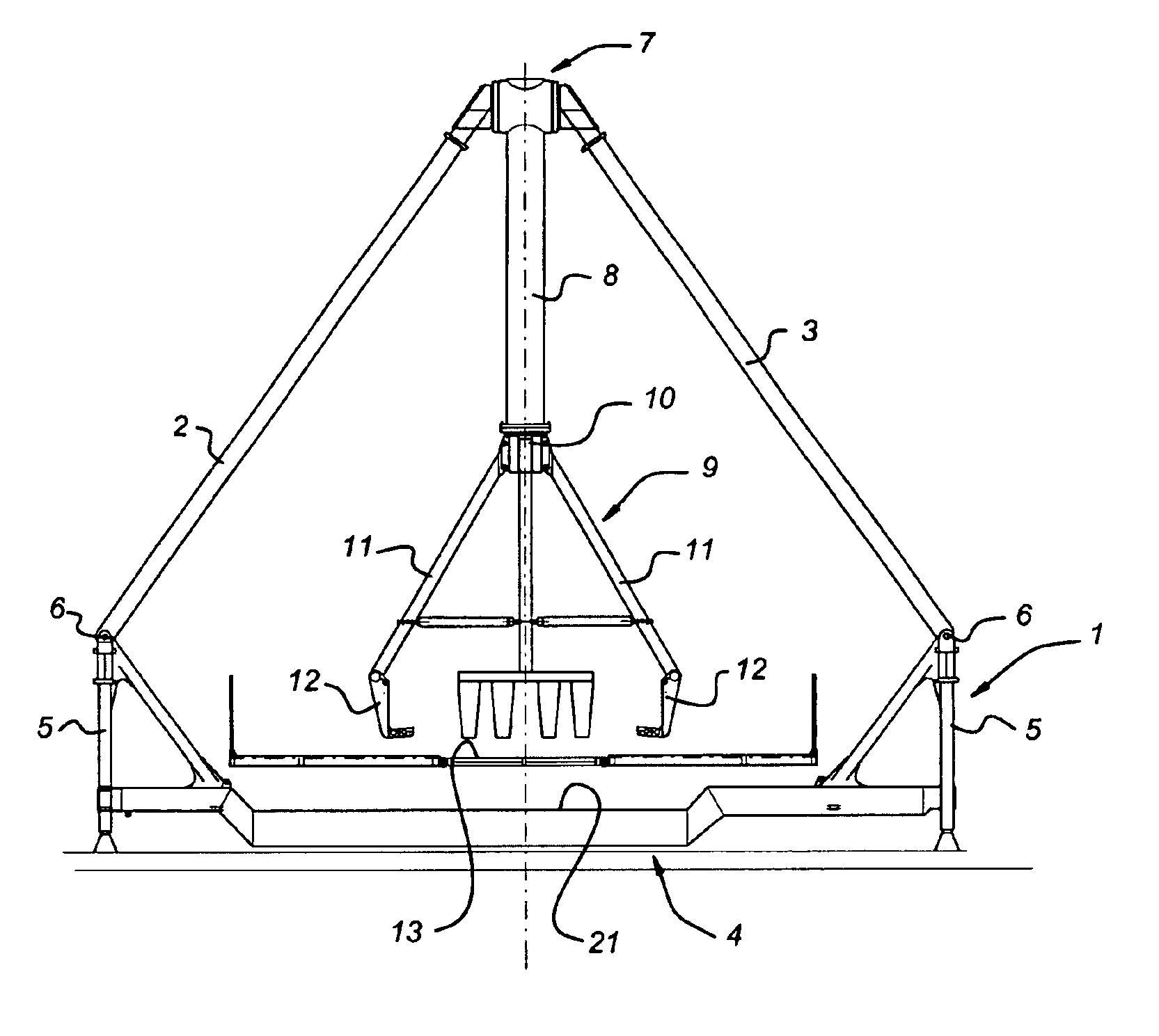
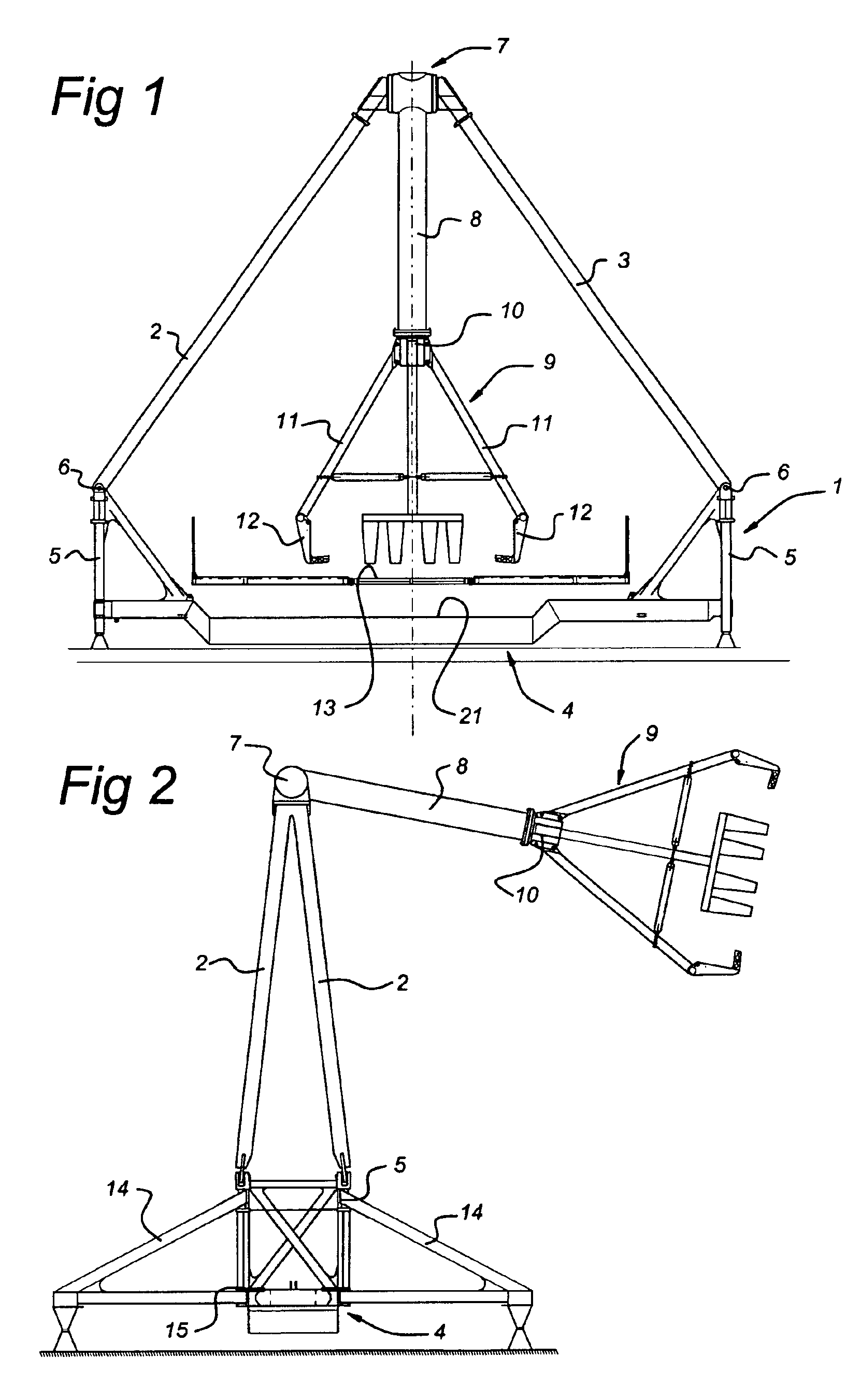
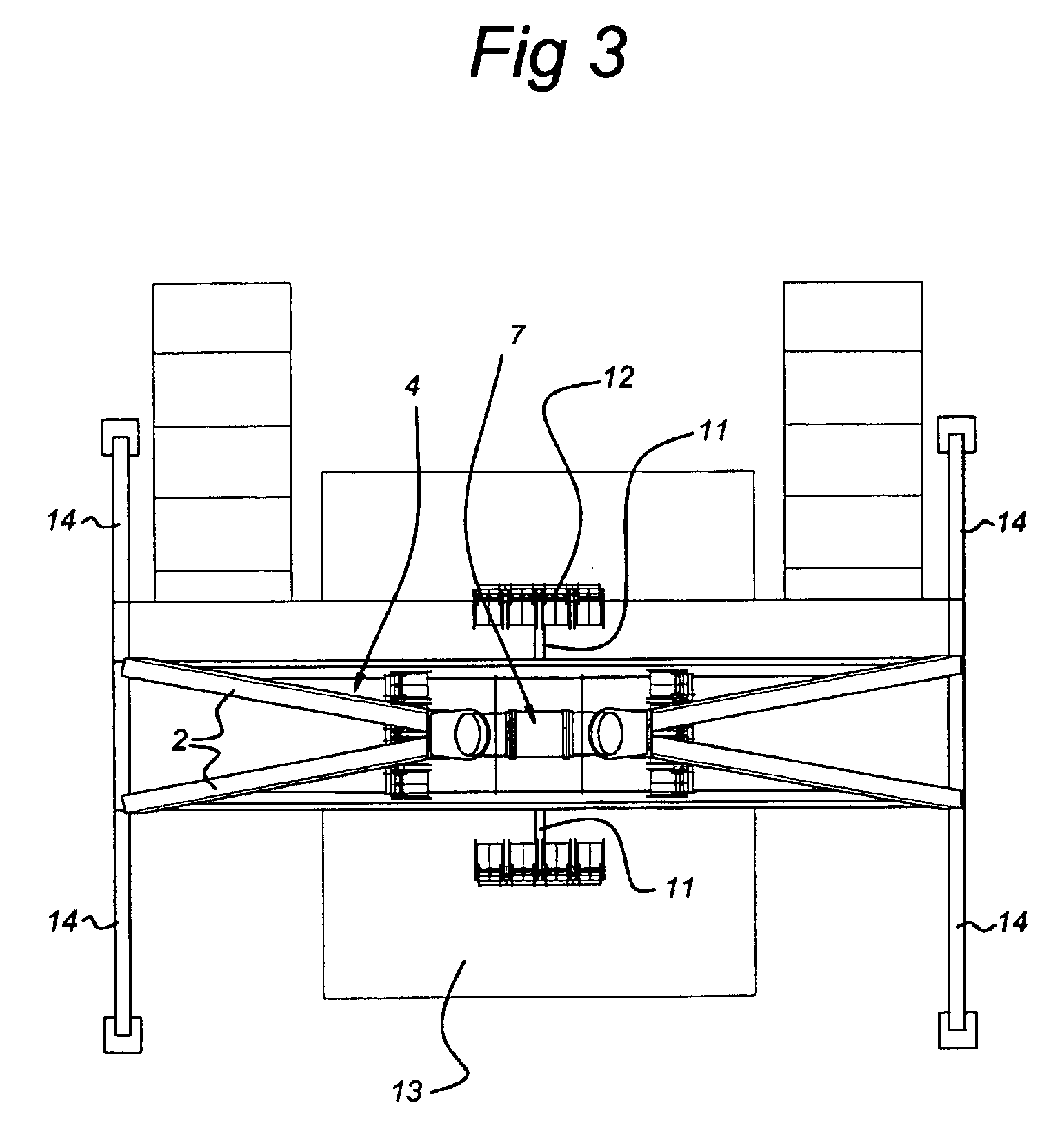
The amusement device according to the invention illustrated in FIG. 1 comprises a frame 1 which has a first pair of support arms 2, a second pair of support arms 3, a trailer 4 and two trestles 5 at the longitudinal ends of the trailer 4. The pairs of support arms 2, 3 are each secured to the trestles 5 by means of hinges 6, the hinge axis of which is oriented transversely with respect to the longitudinal direction of the trailer 4. At their top end, the pairs of support legs 2, 3 support a rotary member 7, the axis of which is oriented in the longitudinal direction of the trailer 4. An arm 8, which bears a receiving device 9 by means of the rotary ring 10, is secured to the rotary member 7. The receiving device 9 has four arms 11, two of which, each bearing a row of seats 12, can be seen in FIGS. 1 and 2.

Furthermore, on the trailer 4 at the level of the recessed section 21 there is a platform 13, from where the occupants can gain access to the seats 12. Stabilizing arms 14, which c...


PUM


Abstract

An amusement device, including a frame made from four support legs which, running obliquely upwards toward one another, at their top end support a rotary member, an arm, one end of which is secured to the rotary member and which can be pivoted between the support legs, and a receiving device for people, which is suspended from the other end of the arm. The support legs, at their bottom end, are secured to a trailer by means of hinges, the hinge axis of which is oriented transversely with respect to the longitudinal direction of the trailer, and the axis of rotation of the rotary member is oriented in the longitudinal direction of the trailer.

Description

BACKGROUND OF THE INVENTION1. Field of the InventionThe invention relates to an amusement device, including a frame made from four support legs which, running obliquely upwards toward one another, at their top end support a rotary member, an arm, one end of which is secured to the rotary member and which can be pivoted between the support legs, and a receiving device for people, which is suspended from the other end of the arm.2. Description of Related ArtAn amusement device of this type is known. Its four support legs are jointed. In the assembled state, these support legs each rest directly on the ground in order to provide the device with the required stability. A reasonable degree of stability is highly important in view of the relatively high imbalance which is generated when the amusement device is operating as a result of the swinging arm with a fully occupied receiving device attached to it.The support legs and various other components of the known amusement device can be tr...

Claims


Application Information

Patent Timeline
Patent Type & Authority Patents(United States)
IPC IPC(8): A63G27/00A63G9/00
CPCA63G9/00A63G27/00A63G2200/00
Inventor KROON, LOUISITO JOHANNES EUSEBIOKROON, ALBERT LOUISITO PHILLIPUS
Owner COBRA BEHEER
Why Eureka
Try Eureka