Method of Constructing High-frequency Vibratory Stress Relief Device for Eliminating Residual Stress of Small Work-piece

a high-frequency vibratory and stress relief technology, applied in the field of vibration stress relief technology, can solve the problems of limited residual stress relief, limited effect of prior art limited vibration modes of traditional low-frequency vibratory stress relief, so as to improve the effect of vibration energy acting effectively eliminating residual stress, and improving the elimination effect of residual stress on the small workpi

Pending Publication Date: 2021-06-03
SHANGHAI MARITIME UNIVERSITY
View PDF0 Cites 1 Cited by
  • Summary
  • Abstract
  • Description
  • Claims
  • Application Information

AI Technical Summary

Benefits of technology

[0030]1. By performing the high-frequency vibratory stress relief on the small work-piece under the natural frequency of the first order axial vibration of the high-frequency vibration energy amplification device, the output vibration energy of the electromagnetic exciter can be amplified. As a result, the vibration energy acting on the small work-piece is improved and the elimination effect of residual stress on the small work-piece via the high-frequency vibratory stress relief can be improved.
[0031]2. The strain gauges are attached on the distribution region of the first principal stress and the second principal stress of the peak residual stress on the small work-piece, which can directly determine the required external vibration stress for the high-frequency vibratory stress relief. As a result, the residual stress can be effectively eliminated via the high-frequency vibratory stress relief.
[0032]3. The sweeping frequency method is not employed to determine the excitation frequency of the high-frequency vibratory stress relief in the present invention. A novel determining method of the excitation frequency of the high-frequency vibratory stress relief is proposed in the present invention. As a result, the efficiency of the high-frequency vibratory stress relief can be improved.
[0033]4. The clamping device of the small work-piece has the advantages of simple structure, simple operation and convenient for the installation and adjustment for the operator.
[0034]5. The bending vibration of the small work-piece can be excited when the high-frequency vibratory stress relief treatment on the small work-piece is conducted under the natural frequency of the first order axial vibration of the high-frequency vibration energy amplification device; the elastic cushion blocks are employed to support the small work-piece at the vibration node lines, and the clamping devices are employed to clamp the small work-piece on the working platform of the high-frequency vibration energy amplification device against the vibration node lines on the small work-piece, so that the small work-piece can vibrate according to its mode shape. At this time, the output strain waveform on the small work-piece has a large peak strain. It implies that the dynamic stress acting on the small work-piece is larger. Therefore the elimination effect of residual stress on the small work-piece via the high-frequency vibratory stress relief can be improved.
[0035]6. The high-frequency vibration energy amplification device with the cone-shaped connecting rod is employed as the basic component of the high-frequency vibratory stress relief device. Compared with the high-frequency vibration energy amplification device with a cylindrical connecting rod, the cone shaped connecting rod adopted in the present invention has a lighter weight if the diameter of the large end of the cone shaped connecting rod is the same as the diameter of the cylindrical connecting rod, benefiting excitation of the high-frequency vibratory stress relief system. Since the driving capacity of the electromagnetic exciter is limited, additional weight of the high-frequency vibration energy amplification device is greater, is a burden for the high-frequency vibratory stress relief device to generate high-frequency vibration. Compared with the high-frequency vibration energy amplification device with the stepped cylindrical connecting rod, the cone shaped connecting rod adopted in the invention can reduce the stress concentration, which is beneficial to improve the service life of the high-frequency vibration energy amplification device. This is because the stepped cylindrical connecting rod tends to produce stress concentration in the transition area, which will reduce the service life of the high-frequency vibration energy amplification device.

Problems solved by technology

As a result, the excitation frequency is generally less than 200 Hz, which shows that the optional vibration modes for the traditional low-frequency vibratory stress relief are very limited.
Meanwhile, the residual stress is eliminated by means of integrally vibrating the work-piece for the traditional low-frequency vibratory stress relief technology, resulting in limited effect of prior art low-frequency vibratory stress relief technology in eliminating the local residual stress for the work-piece or the residual stress for the large complex work-piece.
However, the output vibration energy of the electromagnetic exciter is limited, resulting in limited residual stress relief when the work-piece is directly excited via the electromagnetic exciter.
Firstly, it takes a certain time to determine the excitation frequency of the high-frequency vibratory stress relief, and thus the high-frequency vibratory stress relief is inefficient.
Secondly, the excitation frequency of the high-frequency vibratory stress relief determined via the sweeping frequency method does not consider distribution of the residual stress on the small work-piece.
As a result, ideal residual stress eliminating effect is not obtainable via the high-frequency vibratory stress relief treatment under the excitation frequency determined via the sweeping frequency method.
Thus, it is difficult for the small work-piece to vibrate according to its mode shape.
Therefore, the residual stress eliminating effect of the high-frequency vibratory stress relief on the small work-piece is limited.

Method used


Image

  • Method of Constructing High-frequency Vibratory Stress Relief Device for Eliminating Residual Stress of Small Work-piece
  • Method of Constructing High-frequency Vibratory Stress Relief Device for Eliminating Residual Stress of Small Work-piece
  • Method of Constructing High-frequency Vibratory Stress Relief Device for Eliminating Residual Stress of Small Work-piece

Examples


Embodiment Construction

on will be further described with reference to the accompanying drawings:

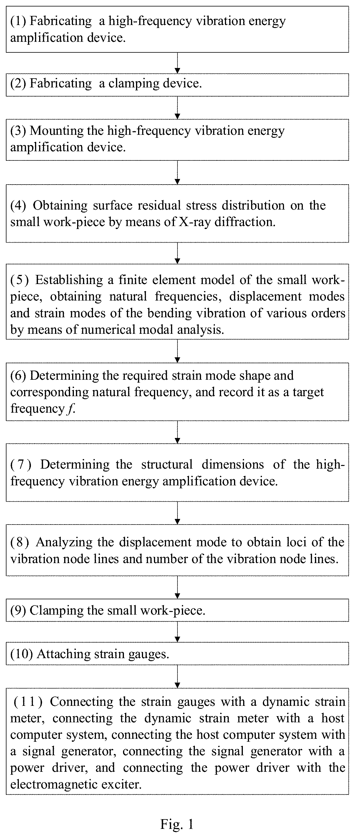
[0054]As shown in FIG. 1, the method of constructing a high-frequency vibratory stress relief device for eliminating residual stress of a small work-piece, the small work-piece having a length a, a width b and a thickness c, comprising the following steps:

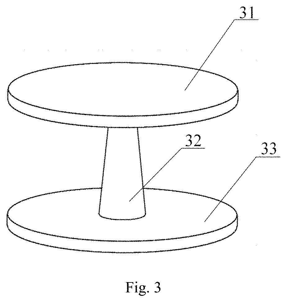
[0055](1) fabricating a high-frequency vibration energy amplification device 3: fabricating the high-frequency vibration energy amplification device 3 by means of integrated molding, wherein the upper part thereof is a working platform 31 in a shape of a cylinder, the middle part is a cone-shaped connecting rod 32, and the bottom part is a supporting platform 33 in a shape of a cylinder; the small end of the cone-shaped connecting rod 32 is connected with the surface center of the working platform 31, and the large end of the cone-shaped connecting rod 32 is connected with the surface center of the supporting platform 33; the high-frequency vibration energy am...


PUM


Abstract

The present invention discloses a method of constructing a high-frequency vibratory stress relief device for eliminating residual stress of a small work-piece. The method comprises the following steps: (1) fabricating a high-frequency vibration energy amplification device; (2) fabricating a clamping device; (3) mounting the high-frequency vibration energy amplification device; (4) obtaining surface residual stress distribution on the small work-piece by means of X-ray diffraction; (5) establishing a finite element model of the small work-piece, obtaining natural frequencies, displacement modes and strain modes of the bending vibration of various orders by means of numerical modal analysis; (6) determining the required strain mode shape and corresponding natural frequency, and record it as a target frequency f; (7) determining the structural dimensions of the high-frequency vibration energy amplification device; (8) analyzing the displacement mode to obtain loci of the vibration node lines and number of the vibration node lines; (9) clamping the small work-piece; (10) attaching strain gauges; (11) connecting the strain gauges with a dynamic strain meter, connecting the dynamic strain meter with a host computer system, connecting the host computer system with a signal generator, connecting the signal generator with a power driver, and connecting the power driver with the electromagnetic exciter. The present invention has the advantage of being able to increase the vibration energy acting on the small work-piece to achieve a better effect of high-frequency vibratory stress relief.

Description

CROSS-REFERENCE TO RELATED APPLICATIONS[0001]The subject application claims priority of the Chinese invention application CN201911217458.1 filed on Dec. 3, 2019 in China. The contents and subject matter thereof are incorporated herein by reference.FIELD OF INVENTION[0002]The present invention relates to the field of vibratory stress relief technology, and relates in particular to a method of constructing a high-frequency vibratory stress relief device for eliminating residual stress of a small work-piece.BACKGROUND ART[0003]Vibratory stress relief technology has a series of advantages such as good processing effect, low energy consumption, short processing time, less environmental pollution and so on. At present, it has been widely employed in various processes of mechanical processing and manufacturing. In addition, it has become an energy-saving and environment-friendly residual stress relief technology. A speed-adjustable motor is adopted as the exciter for the traditional low-fr...

Claims


Application Information

Patent Timeline
Patent Type & Authority Applications(United States)
IPC IPC(8): B23K26/382B23G1/02G06F30/23
CPCB23K26/382G06F30/23B23G1/02C21D10/00C22F3/00B23K26/362B23K26/40B23K2103/04B23K2103/10
Inventor GU, BANGPINGWANG, PINGWU, HAORANHU, XIONGZHUANG, JIAYIWANG, SIQIHUO, ZHIPENGWANG, ZHONGSHAN
Owner SHANGHAI MARITIME UNIVERSITY
Why Eureka
Try Eureka