Apparatus and method for detection of railroad wheel and bearing temperature

a technology of bearings and apparatus, which is applied in the direction of optical radiation measurement, instruments, sensing radiation from moving bodies, etc., can solve the problems of increasing the voltage or current generated by the detector, the limitation of the detector to identifying the intensity or power, and the limitations of prior art systems, so as to improve the operation of the railway system, improve the detection effect, and reduce the instances of false heat detection

Inactive Publication Date: 2005-03-29
PROGRESS RAIL SERVICES
View PDF28 Cites 46 Cited by
  • Summary
  • Abstract
  • Description
  • Claims
  • Application Information

AI Technical Summary

Benefits of technology

The apparatus and method of the present invention has a number of advantages over the prior art. The present invention determines a temperature range or a temperature of the wheel or bearing and is not susceptible to variations in the amplitude, intensity or power of the detected infrared radiation. As such, the presence of snow, wind or rain that attenuates the emitted radiation does not necessarily impact the accurate measurement of the temperature. Furthermore, the presence of direct sunlight that increases the amount of detected infrared radiation does not create a false indication of the temperature. Additionally, a detector according to the invention is not susceptible to high G-forces. The apparatus and method of the invention may be deployed as a new unit or may be incorporated into a retrofit to existing hot wheel or hot bearing detection systems. The apparatus and method of the invention provide for improved detection of a temperature range or temperature of the traversing wheel or bearing thereby reducing the instances of false heat detection or non-detection of a hot wheel or hot bearing. As such the apparatus and method of the invention improves the operation of railway systems by reducing the likelihood of a train derailment or a costly unnecessary stop.

Problems solved by technology

In such prior art systems, an increase in the magnitude of the radiation within the wavelength range results in an increase in the voltage or current generated by the detector.
In such systems, the detector is limited to identifying the intensity or power of the infrared radiation within the predefined wavelength range.
While such a design provides an indication of a hot wheel or hot bearing that results in a voltage or current that exceeds the predetermined threshold voltage or current level, the prior art systems have several limitations in the application to railway systems that detect the heat of a traversing railway vehicle's wheel or bearing.
This results in an inaccurate detection of the hot wheel or bearing condition.
When this occurs, there is potential for disaster as the undetected hot wheel or hot bearing may fail causing a potentially dangerous situation including a train derailment.
Another such external source which negatively impacts the operation of prior art detection systems is the sun.
In this situation, the filtered infrared radiation saturates the infrared detection device with considerable infrared radiation from the sun causing the detector to detect higher levels of heat thereby resulting in a false hot wheel or bearing alarm.
The piezoelectric effect causes the device to produce a false heat signal or increased level of voltage output.
In these cases, the false hot wheel or bearing alarm may result in an unnecessary and unscheduled stop of the train to investigate and perform maintenance.
False stops are both time-consuming and costly as they may also cause substantial disruption in train schedules.
Furthermore, an improved system will not be susceptible to inaccurate temperature measurements when the detector is exposed to high levels of direct sunlight.

Method used


Image

  • Apparatus and method for detection of railroad wheel and bearing temperature
  • Apparatus and method for detection of railroad wheel and bearing temperature
  • Apparatus and method for detection of railroad wheel and bearing temperature

Examples


Embodiment Construction

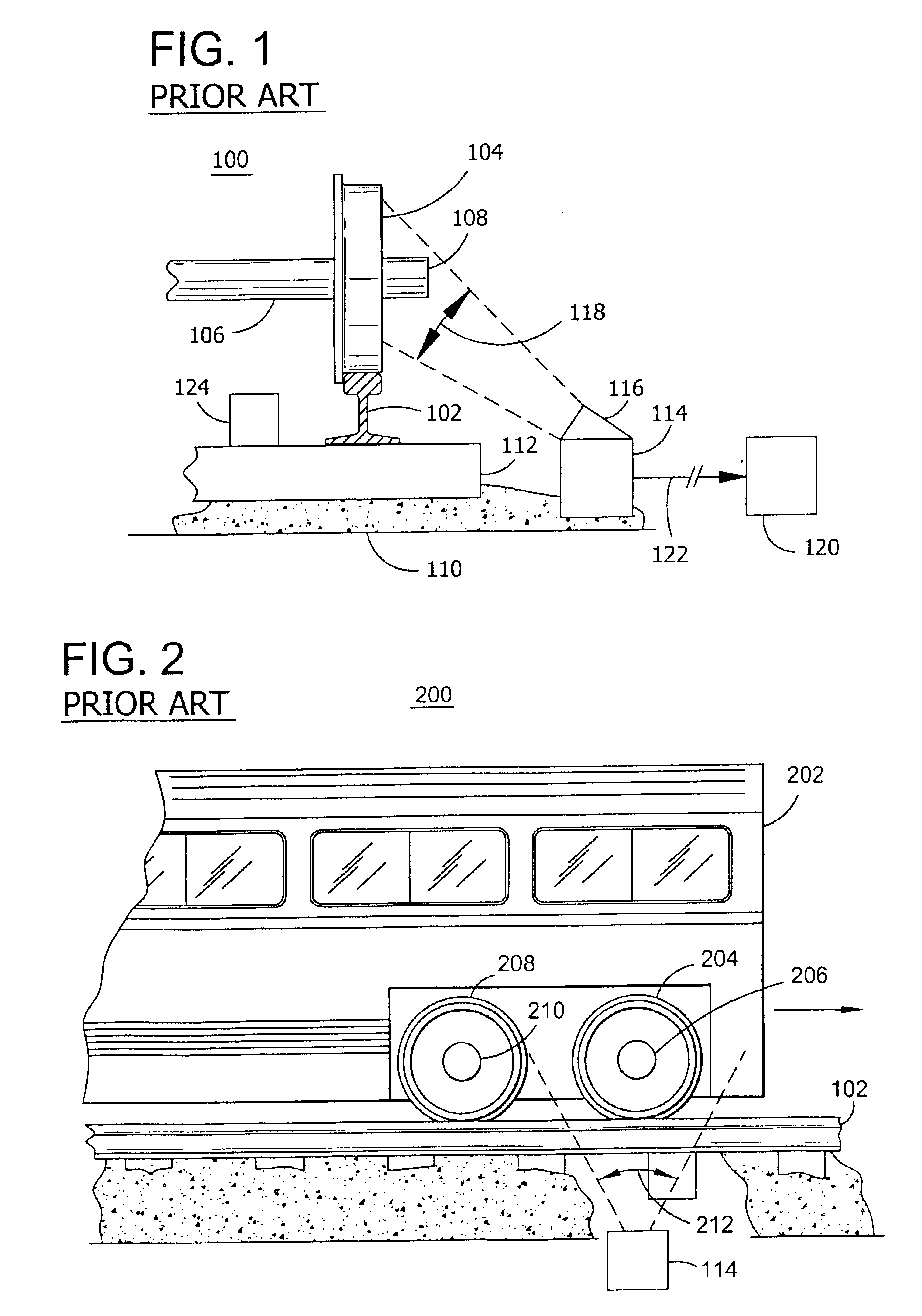
Referring to FIG. 1, a prior art hot wheel or bearing detection system 100 is located near a railroad rail 102. A railroad track is comprised of the railroad rail 102 and a crosstie 112 that is mounted on an earthen structure 110 such as gravel. Rail 102 is mounted on a plurality of crossties 112. A railway vehicle (not shown), includes one or more axles 106 which are connected to wheel 104 by bearing 108. As the railway vehicle moves, wheel 104 traverses rail 102. A hot wheel or hot bearing detector 114 is located in close proximity to rail 102 such as to enable detector 114 to detect a temperature range or a temperature of the wheel 104 or bearing 108 of a railway vehicle traversing rail 102. Detector 114 is configured with a scanner 116 that collects the heat generated by objects within the detection zone 118. Wheel sensor 124 is located inside of rail 102 to detect the presence of a railway vehicle or wheel 104 and axle 106 above the wheel sensor 124. Wheel sensor 124 provides a...


PUM


Abstract

An apparatus and method is provided for detecting a temperature range or a temperature of a railroad train wheel or bearing wherein infrared radiation radiating from the wheel or bearing of a train traversing a railroad track is indicative of a temperature range of the wheel or bearing. The apparatus comprises a sensor for sensing infrared radiation radiating from the wheel or bearing within two or more infrared wavelength ranges. The sensor generates signals indicative of the sensed infrared radiation in each of the wavelength ranges. A processor determines a temperature range or a temperature of the wheel or bearing from the generated signals. The method detects a temperature range of a railroad train wheel or bearing wherein infrared radiation radiating from the wheel or bearing of a train traversing a railroad track is indicative of the temperature range of the wheel or bearing. The method includes sensing infrared radiation radiating from the wheel or bearing within two or more wavelength ranges of the infrared radiation. Signals are generated that are indicative of the sensed infrared radiation in each infrared wavelength range. A temperature range or a temperature of the wheel or bearing is determined from the generated signals.

Description

BACKGROUND OF THE INVENTION1. Field of the InventionThis invention relates generally to the detection of a temperature range or a temperature of a wheel or bearing of a railway vehicle. More specifically, the invention relates to collecting an infrared (IR) radiation wavelength spectrum radiating from the wheel or bearing of a train traversing a railroad track that is indicative of the temperature range or the temperature of the wheel or bearing.2. Brief Description of the Prior ArtIn order to protect against railroad car wheel or bearing failures, most railroads utilize heat detectors along their rights of way and in close proximity to their railroad tracks. Such detectors view, through infrared scanners, the bearing and wheel of a passing train. If an overheated wheel or bearing is detected, an alarm is triggered to alert the train operator that an overheated wheel or bearing has been detected.The infrared scanner and associated circuits for detecting an overheated wheel or bearin...

Claims


Application Information

Patent Timeline
Patent Type & Authority Patents(United States)
IPC IPC(8): G01J5/00G01J5/60
CPCG01J5/0022B61K9/06G01J5/602
Inventor BARTONEK, MARK
Owner PROGRESS RAIL SERVICES
Why Eureka
Try Eureka