Electrical power distribution suitable for a substantially underwater system

US6873063B1Inactive Publication Date: 2005-03-29ALPHA THAMES LTD

Image

  • Electrical power distribution suitable for a substantially underwater system
  • Electrical power distribution suitable for a substantially underwater system
  • Electrical power distribution suitable for a substantially underwater system

Examples


Embodiment Construction

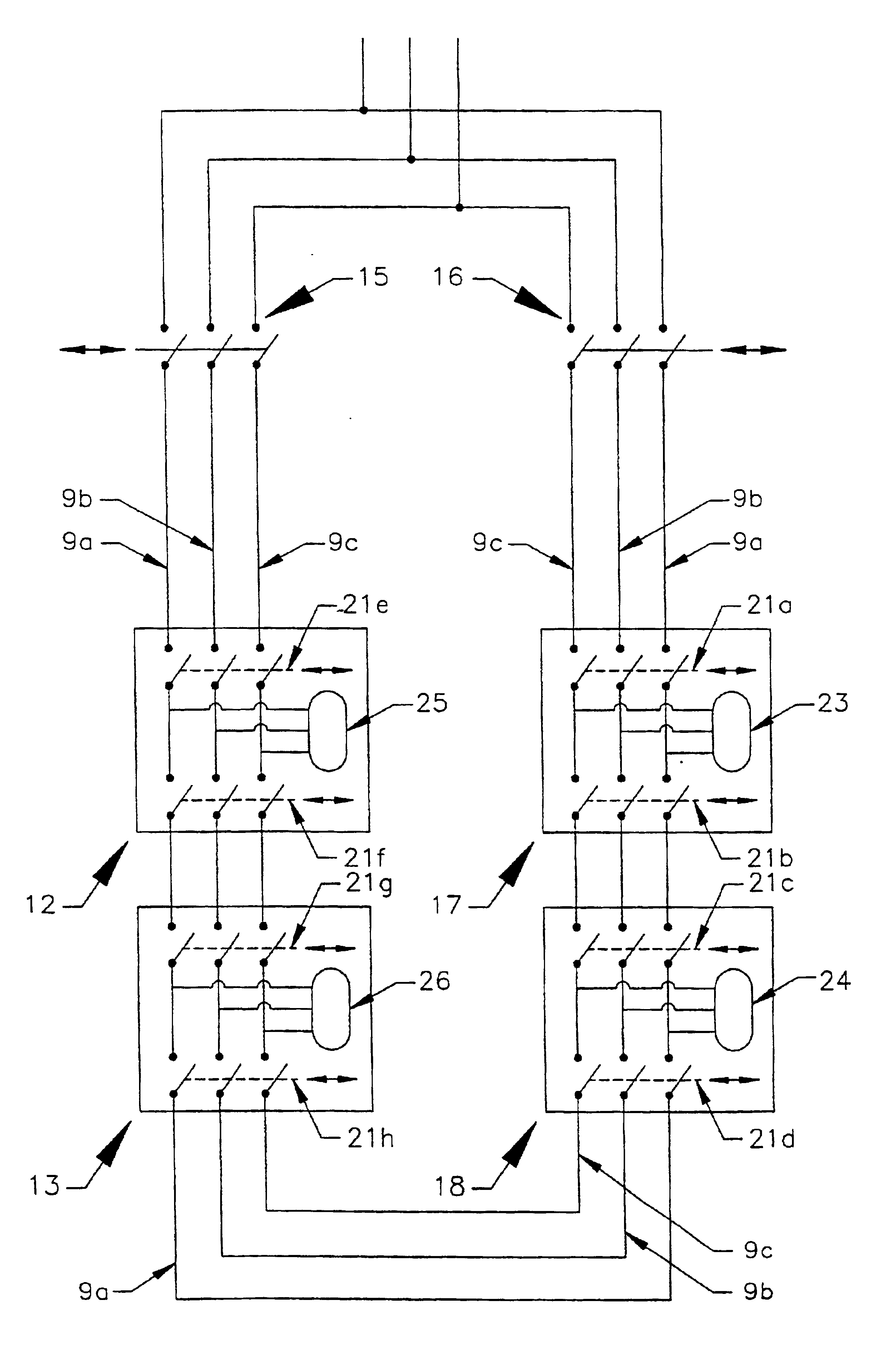
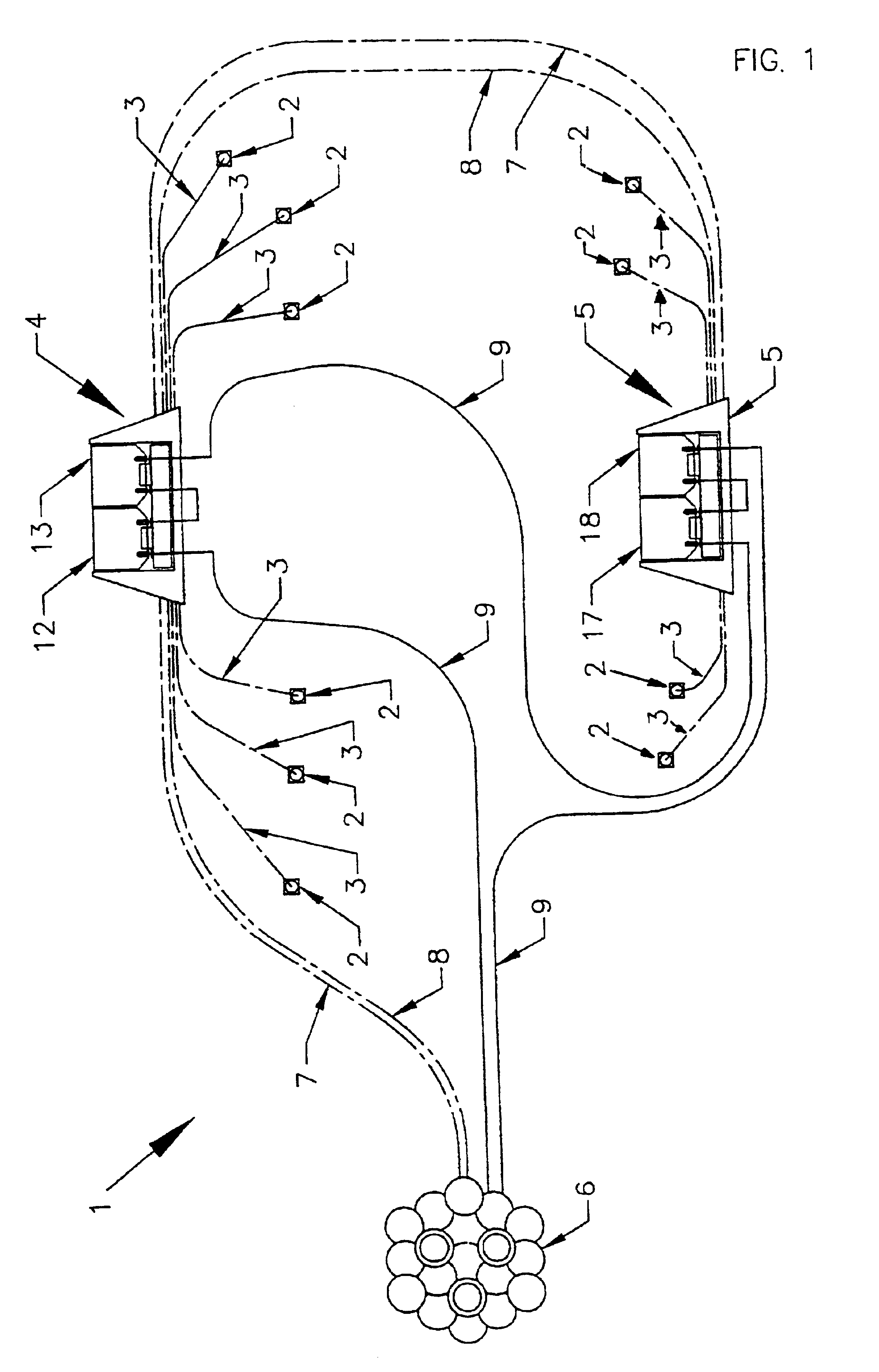
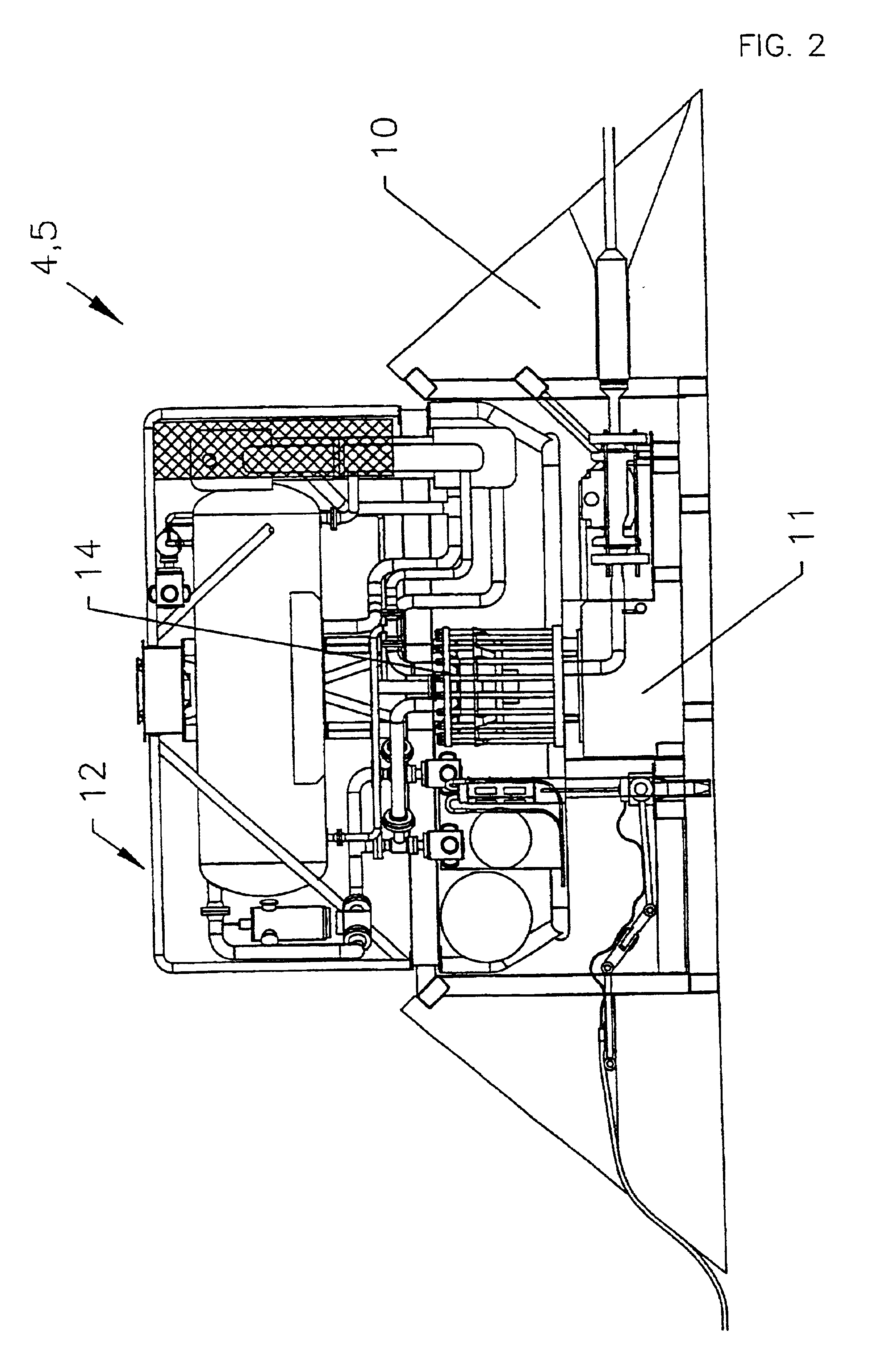
Referring to FIGS. 1 and 2 of the accompanying drawings, a subsea field 1 includes wells 2 for removing a fluid mixture comprising water and oil / gas from reservoirs beneath the seabed. The wells 2 are connected by underwater flow lines 3, such as rigid and / or flexible pipelines, to modular subsea or seabed sub-systems 4,5 of a substantially underwater system where the oil and / or gas may be extracted from the fluid mixture and the oil / gas flows under well pressure or is pumped to a host facility 6 via flow lines 7,8, the flow lines 7,8 connecting the modular seabed sub-systems 4,5 in series to the host facility 6. A plurality of wells may be connected to a template before being connected to a modular seabed sub-system. The host facility may be, for example, onshore or on a fixed or a floating rig. The host facility 6 has an integrated power and control line 9 connecting the modular seabed sub-systems 4,5 in series to form a circuit, the host facility 6 providing the power and control...


PUM

PropertyMeasurementUnit
electrical power distributionaaaaaaaaaa
poweraaaaaaaaaa
series power distributionaaaaaaaaaa

Abstract

A substantially underwater system comprises a plurality of retrievable substantially autonomous subsea modules (12, 13, 17, 18) and switchgear (15, 16, 21a . . . h). A host facility (6) and the modules are connected in series so as to form a circuit, the host facility providing power to all of the modules. Operation of the switchgear electrically isolates a module or a plurality of serially adjacent modules so that the module or modules can be removed without cutting off the power supply to any of the remaining modules of the system. Module based parts of the switchgear (21a . . . h) only or a combination of module based parts (21a . . . h) and host facility based parts (15, 16) of the switchgear are actuated depending on which module or modules are isolated and removed.

Description

BACKGROUND OF THE INVENTIONThe present invention relates to electrical power distribution suitable for a substantially underwater system used in an underwater oil / gas field.Conventional oil / gas fields have a plurality of wells linked to a host facility which receives the oil / gas via flow lines. If the underwater oil / gas field includes underwater processing units between the wells and the host facility, it would be useful to be able to reconfigure or replace an underwater processing unit without having to power down the other underwater processing units in the field and thereby significantly reduce production from the field.Presently, any underwater processing units which require power / controlling rely on at least one expensive and complex multiple conduit hydraulic line to connect each part to a host facility on / above the sea surface or onshore.SUMMARY OF THE INVENTIONIt is an object of the present invention to provide an improved method and system which alleviates / solves problems a...

Claims


Application Information

Patent Timeline
29 Mar 2005
Publication
US6873063B1
IPC
B01D17/00; B01D19/00; E21B43/017; E21B43/00; E21B43/34; E21B43/36; H02J4/00
CPC
B01D17/00; B01D19/0063; E21B43/017; E21B43/36; H02J4/00; B01D17/0208; B01D17/0211; B01D17/0214
Inventors
APPLEFORD, DAVID ERIC; LANE, BRIAN WILLIAM