
Antenna system utilizing elevated, resonant, radial wires

a technology of radial wires and elevated wires, which is applied in the direction of antenna details, antennas with plural divergent straight elements, antennas, etc., can solve the problem of not revealing the combination of top loading wires, and achieve the effect of optimizing the efficiency of radiation capture and maximizing the efficiency of radiation

Inactive Publication Date: 2005-03-29
GATESAIR
View PDF5 Cites 15 Cited by
  • Summary
  • Abstract
  • Description
  • Claims
  • Application Information

AI Technical Summary

Benefits of technology

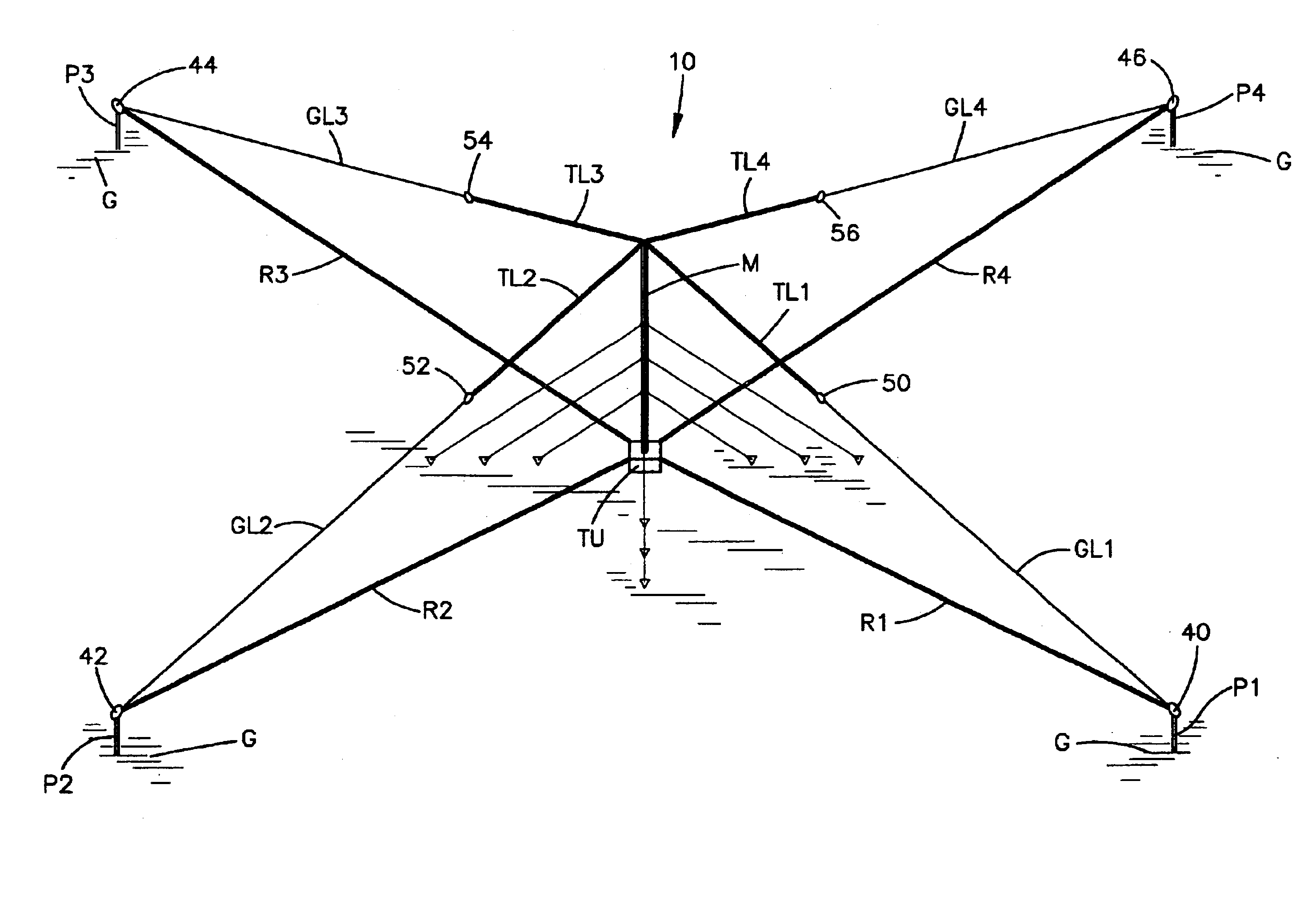
The present invention contemplates the provision of an medium wave antenna system constructed so as to be smaller and lighter than a full size, quarter wavelength antenna and, as such, may be transportable. The system has the capability of generating far field intensities on the order of 70% of a full size antenna over normal soil conductivity of 4-8 milliohms per meter in the operating frequency range of 1200 to 1700 kilohertz. This is obtained by constructing an antenna in accordance with the present invention wherein the radiation efficiency is maximized by dramatically reducing ground resistance losses compared to conventional antenna designs. For example, in one version, top loaded wires are located directly above resonant radial wires so that substantially all of the electric field lines are efficiently captured.
Moreover, the present invention contemplates a compact antenna system having a lower radiation resistance than a full size one quarter wavelength antenna system which makes reduction of ground loss resistance more important than with a full size antenna. Ground losses are reduced and high efficiency is achieved by elevating the radial wires above the ground surface directly below the top loading wires and electrically resonating the radial wires with a series inductor. It has been found in practicing this invention that up to 95% of the RF current flowing in the vertical radiator may be captured by the resonant radial system instead of being dissipated in the ground resistance.

Problems solved by technology

Also, they do not disclose that such top loading wires be provided in combination directly above the elevated resonant radial wires.

Method used


Image

  • Antenna system utilizing elevated, resonant, radial wires
  • Antenna system utilizing elevated, resonant, radial wires
  • Antenna system utilizing elevated, resonant, radial wires

Examples


Embodiment Construction

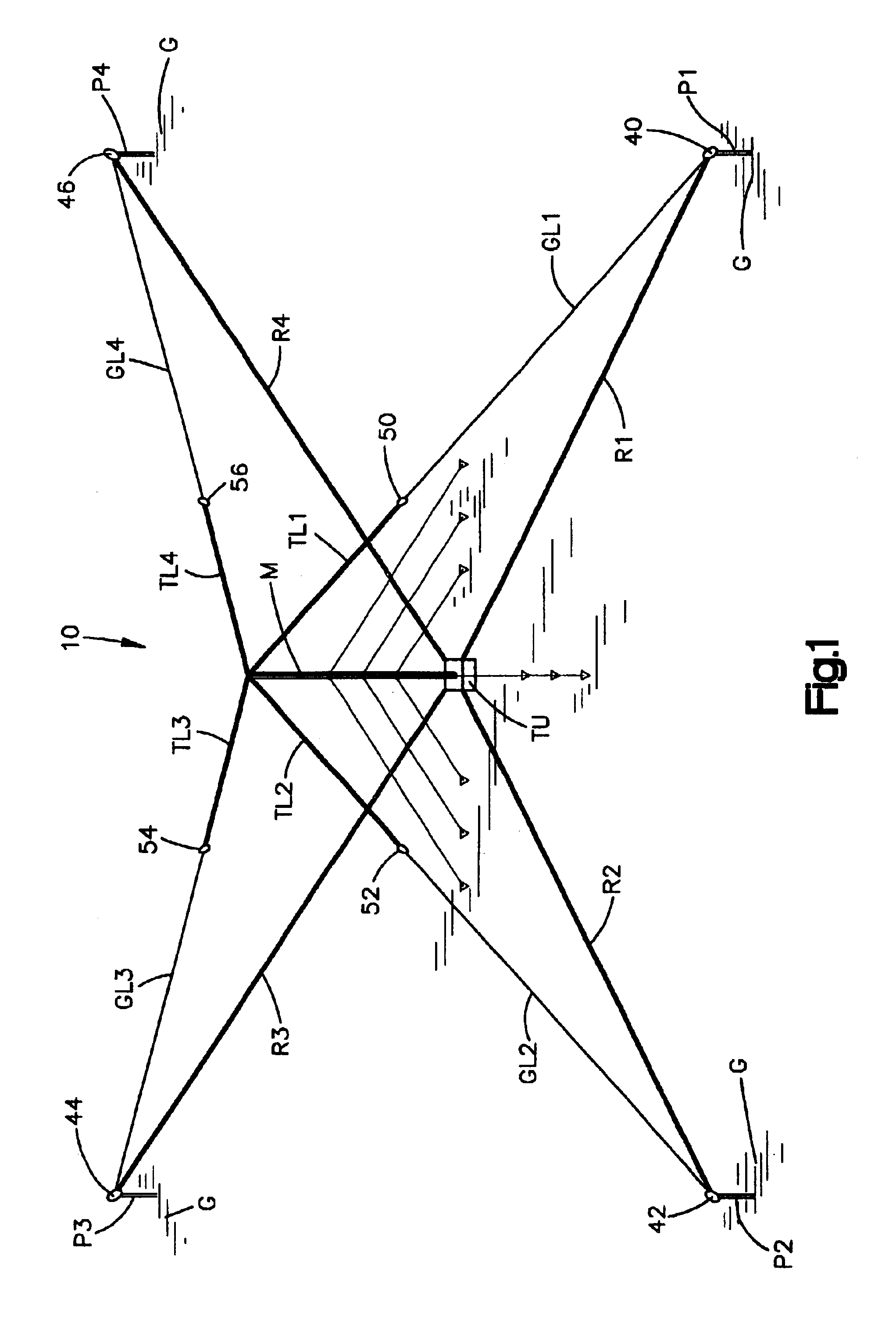
Reference is now made to FIG. 1 which illustrates the antenna system 10 constructed in accordance with the present invention. The following is a brief overall description of the antenna as shown in FIG. 1. This description will be followed by a description of the theory involved in the operation of the antenna and this, in turn, will be followed by a detailed description of the structural and electrical features of the antenna.

As shown in FIG. 1, the antenna system 10 includes a vertically extending, electrically conductive mast M which extends upwardly from a tuning unit TU (to be described in greater detail hereinafter). The mast terminates in an upper end from which extends four radially extending top loading wires TL1, TL2, TL3 and TL4. Four radial wires R1, R2, R3 and R4 extend radially outward from the mast and protrude from the tuning unit TU. These radial wires are elevated above the level of the earth ground G.

Having briefly described the system, attention is now directed t...


PUM


Abstract

An antenna system is presented including an electrically conductive radiating mast that extends generally vertical relative to earth ground. The mast has a lower end for receiving RF energy for radiation thereby at an operating RF frequency and an upper end. A plurality of N radial, electrically conductive, wires are provided with each having an inner end and an outer end. The inner ends of the radial wires are electrically connected together and located proximate to the vertical mast. The radial wires are elevated throughout their lengths above the level of earth ground and extend radially outward from the vertical mast. A tuning device, such as an adjustable inductor, is connected to the radial wires for adjusting the impedance thereof such that the radial wires resonate at the operating frequency.

Description

BACKGROUND OF THE INVENTION1. Technical FieldThe present invention relates to the art of RF broadcasting antenna systems and, more particularly, to such a system intended for medium wave broadcasting employing a vertically oriented radiator in the form of a mast, together with a plurality of elevated resonant radial wires.2. Description of the Prior ArtAntenna systems employing a vertical radiator together with radial wires are known in the art. This, for example, includes an article entitled “Ground Systems As A Factor In Antenna Efficiency” by G. H. Brown, R. F. Lewis and J. Epstein in the Proceedings of the Institute of Radio Engineers, Volume 25, No. 6, June 1937. Such a system with elevated radial wires is described in an article entitled “AM Broadcast Antennas With Elevated Radial Ground Systems” by A. Christman and R. Radcliff at 0018-9316 / 88 / 0300-0075$01.00, Copyright 1988 IEEE, note pages 75-77.It is to be noted that the above publications do not describe that the radial wi...

Claims


Application Information

Patent Timeline
Patent Type & Authority Patents(United States)
IPC IPC(8): H01Q9/04H01Q9/44H01Q9/36H01Q9/34
CPCH01Q9/34H01Q9/44H01Q9/36
Inventor MENDENHALL, GEOFFREY NORMAN
Owner GATESAIR
Learn More